Elecraft KRC2 Manual User Manual
Page 11
11
Install the subminiature DPDT slide switch S5 on the bottom side of the PCB. Make sure the
switch is firmly seated against the board when soldering. After installing the switch, move its
handle to the position closest to J2.
Install a 16-pin dual-row header at W1-W8 on the bottom side of the PCB. The short pins
are inserted into the PCB. The header must be firmly seated against the board when soldering.
Install a 16-pin dual-row header at W12-W19 on the bottom side of the PCB. The short pins
are inserted into the PCB. The header must be firmly seated against the board when soldering.
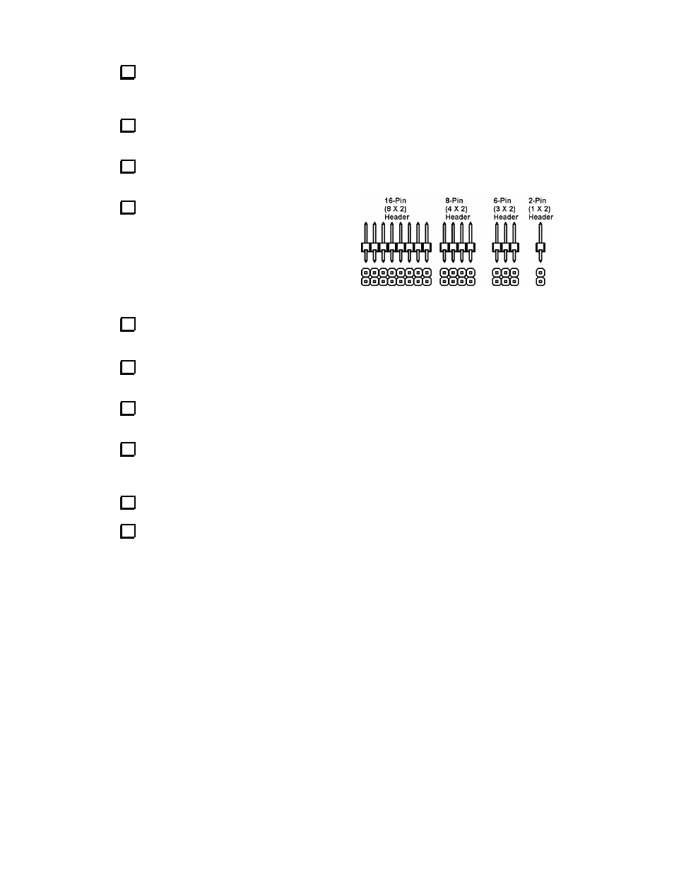
Locate the remaining 16-pin dual-row header.
Cut the header into three pieces so that you have one
8-pin dual row header, a six-pin header and a 2-pin
header. This is best done using diagonal cutters. Cut
the header on the side, then bend the portion to be
cut off away from the rest of the header. The two
pieces should snap apart somewhat cleanly. Discard
the 2-pin header.
Install the 8-pin dual-row header at W20-W23 on the bottom side of the PCB. The short pins
are inserted into the PCB. The header must be firmly seated against the board when soldering.
Install the 6-pin dual-row header at W9-W11 on the bottom side of the PCB. The short pins
are inserted into the PCB. The header must be firmly seated against the board when soldering.
Locate the shorting headers. Install 14 shorting headers on the dual-row headers W9-W19
and W21-W23 by plugging them onto the header pins. Do not install a jumper at W20 at this time.
Install electrolytic capacitor C12 (220 µF) on the bottom side of the PCB. The (+) lead of
C10 must be installed in the hole marked "+". The (+) lead is usually longer than the (-) lead. The
(-) lead is identified by a stripe on the body of the capacitor.
Install the DC barrel jack (J3) on the bottom side of the PCB.
Install J2, a male PC-mount DB9 connector on the bottom side of the PCB. This position is
next to the side of the PCB. The connector will “snap” into the board as its mounting tabs “grab”
the board. Be sure you have installed the MALE connector (with pins) before soldering the
connector pins onto the board.
Figure 2