Elecraft KRC2 Manual User Manual
Page 22
22
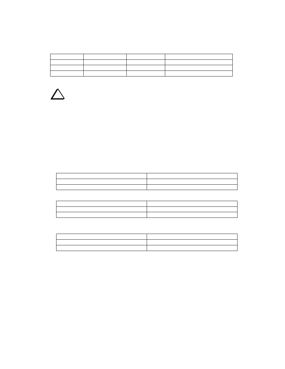
When the KRC2 is set to receive band data in an analog mode, the jumpers associated with the
selected input should be removed from the J2 connection. The analog input should then be fed into
the KRC2 using the PC connector. Use J1 pin 1 for the ground return connection. These settings
and connections are listed in Table 5.
Analog Input
Remove Jumper(s)
J1 Pin for input
Comments
8R / AN1
W19
9
0 - 10 volt input range
VRDET / AN2
W17
7
0 - 5 volt input range
ALC / AN3
W20
4
0 - 10 volt input range
Table 5
i
Important! Do NOT use the jumper connections to bridge external RS-232
serial port signals. This may cause serious damage to your radio when moving the
KRC2 from one radio to another. The preferred method is to provide the bridging
in the cable used with the radio needing it. This specifically applies to Kenwood
transceivers.
Rig-Specific Setup
The following settings are suggested for each radio. Note that these are suggested that have been
successful for users. Other setups are possible and may be preferred. Note that W4 and W5 should
be set as required for the desired bandmap configuration.
Elecraft K2.
• K2 AuxBus used for band, serial port for control and data. PC logging program in use:
Installed
Removed
W1, W2, W3, W6, W7, W8
W9, W10, W16-W19, W21-W23
W11-W15, W20
• K2 AuxBus used for band, serial port for control and data. Stand-alone (no PC):
Installed
Removed
W6
W1, W2, W3, W7, W8
W9 -W19, W21-W23
W20
• K2 serial port used for band, data and control communications. PC logging program in use:
The KRC2ACC may use this setup for communications with the K2.
Installed
Removed
W3
W1, W2, W6, W7, W8
W9, W10, W16-W19, W21-W23
W11 – W15, W20