Elecraft KRC2 Manual User Manual
Page 14
14
Visual Inspection: Using a magnifying glass, examine the entire board for unsoldered pins,
solder bridges, broken leads, or backward diodes or ICs. Reheat any suspect joints This simple
check could save you hours of troubleshooting later.
Case Assembly
Locate the case top cover. This piece has three rectangular holes punched into the face.
Locate a 4-40 x 3/16” flat head screw. Push it through the hole on the top of the case, holding
it in place with a finger as you turn the case over. Locate two #4 internal-tooth lock washers. Slide
both lock washers onto the screw shaft inside the case. Locate the 1/4 x 3/16” round threaded
standoff. While holding the screw with a Philips screwdriver, screw the standoff onto the screw.
Tighten the assembly.
Insert the circuit board assembly into the case with the pushbutton switches and LED passing
through the rectangular holes in the case. Secure the circuit board to the case with a single 4-40 x
3/16” pan head Philips screw and #4 lock washer.
Locate the four #4 male-female hex standoffs. These are used to secure the DB9 connectors
to the case. Screw each standoff through one of the mounting holes next to the DB9 connectors in
the end of the case into the threaded DB9 assemblies.
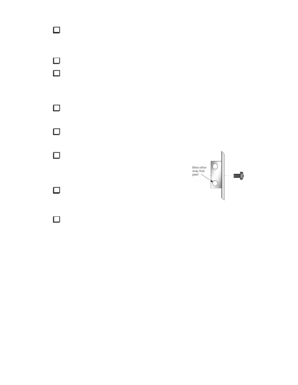
Locate the two “2-D” fasteners. These are used to secure the
case top and bottom. Note that on the side of the fastener with
two screw holes, there is more space to one side of the holes than
the other. The side with the most space will face away from the
circuit board.
Using two 4-40 x 3/16” flat-head screws, attach one “2-D”
fastener to the case top just above the J1 DB9 connector. Make
sure the wide side of the fastener side faces away from the circuit
board.
Attach the second “2-D” fastener, using two 4-40 x 3/16” flat head screws, to the end of the
top case away from the DB9 connectors. Follow the same procedure as in the previous step.
Again, the wide side of the fastener should face away from the circuit board.
Figure 5