Elecraft KRC2 Manual User Manual
Page 20
20
KRC2 Jumper Configuration
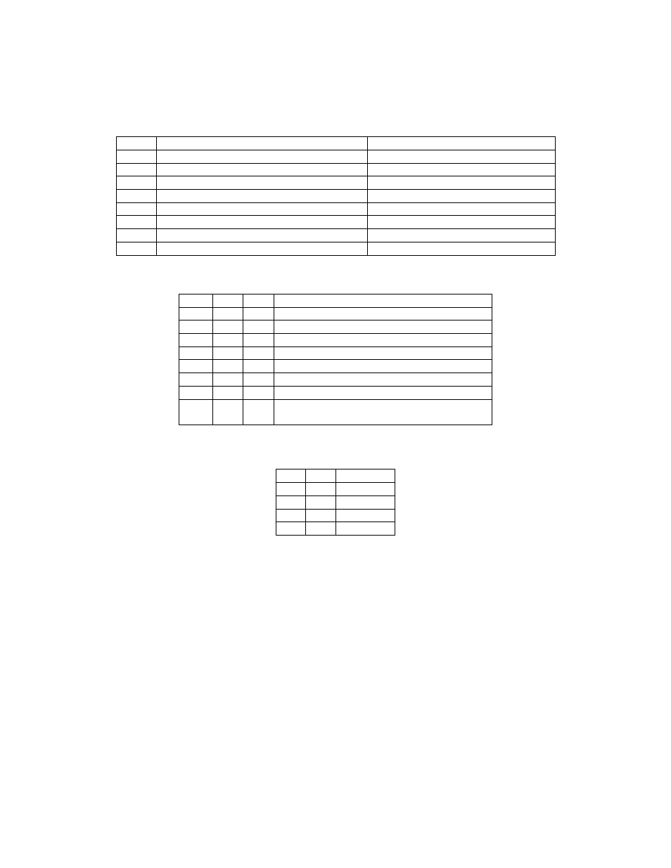
There are 21 jumpers in the KRC2 allowing for a wide range of device options. The W1-8 block,
located near the front of the case, controls device configuration for different radio setups and
driver output logic. Table 1, Table 2 and Table 3 show the different settings.
Jmpr
Jumper Out (default)
Jumper In
W1
Use digital band decoding
Use analog band decoding
W2
Band decode option bit 1 - see Table 2
Band decode option bit 1 - see Table 2
W3
Band decode option bit 2 - see Table 2
Band decode option bit 2 - see Table 2
W4
ACn drivers use 1 of 3 decoding
ACn drivers use binary coding
W5
Xvtr drivers use 1 of 3 decoding
Xvtr drivers use binary decoding
W6
No auto-report mode
Place XCVR in auto-report mode
W7
Data Rate bit 0 – see Table 3
Data Rate bit 0 – see Table 3
W8
Data Rate bit 1 – see Table 3
Data Rate bit 1 – see Table 3
Table 1
W1
W2
W3
Band decode source
Out
Out
Out
AuxBus Mode – K2 operation
Out
Out
In
Serial Port Mode – K2 or Kenwood operation
Out
In
Out
Digital Input through J4
Out
In
In
Not used
In
Out
Out
Analog input using ALC input (DB9 pin 4)
In
Out
In
Analog input using 8R input (DB9 pin 9)
In
In
Out
Analog input using VRDET input (DB9 Pin 7)
In
In
In
Analog input using 8R input (DB9 pin 9) with
reference voltage on ALC input (DB9 pin 4)
Table 2
W8
W7
Data Rate
Out
Out
4800
Out
In
9600
In
Out
19200
In
In
4800
Table 3