Elecraft KPA500 Kit Assembly Manual User Manual
Page 37
36
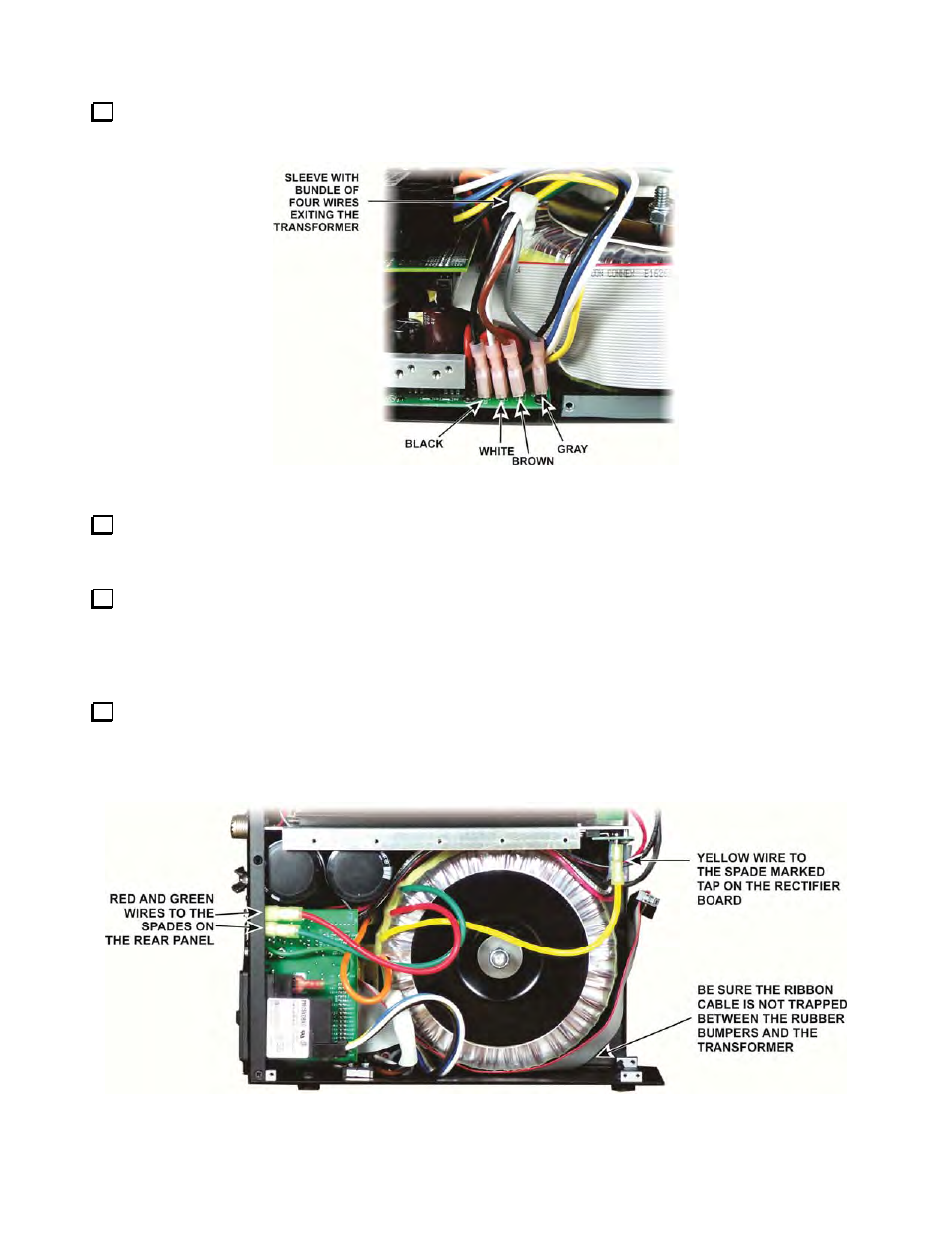
The transformer primary winding connections exit the transformer in a white sleeve. Connect them to the
power supply module board as shown in Figure 52.
Figure 52. Connecting the Transformer Primary Windings to the Power Supply Module.
Replace the left side panel using the screws you removed earlier. Be sure to reconnect the interlock switch
to the power supply module (see Figure 35 on page 26) and ensure the interlock switch cable is not trapped
between the side panel and the heat spreader.
Stand the KPA500 on the left side and loosen the bolt and Nylock nut slightly so that the weight of the
transformer bears on the rubber bumpers. Be sure the wide ribbon cable is not caught between the bumpers
and the transformer. T
ighten the bolt and Nylock nut just until the transformer no longer moves when pressed
against the bottom, and then turn the nut between one and two turns further. This will result in about 55 in-
pounds of torque on the nut and bolt. If you have a torque wrench, you may use it, but it is not necessary.
Set the KPA500 on its bottom feet. You should now have three loose transformer wires remaining. These
are taps that are used to compensate for variation in your local mains voltage as described in your Owner’s
Manual. The active tap is connected to the rectifier board and the two unused taps are connected to the terminals
on the rear panel to keep them out of the way and to avoid short circuits. Connect them as shown in Figure 53
until you have completed assembling your KPA500.
Figure 53. Connecting Transformer Taps.