Elecraft KPA500 Kit Assembly Manual User Manual
Page 29
28
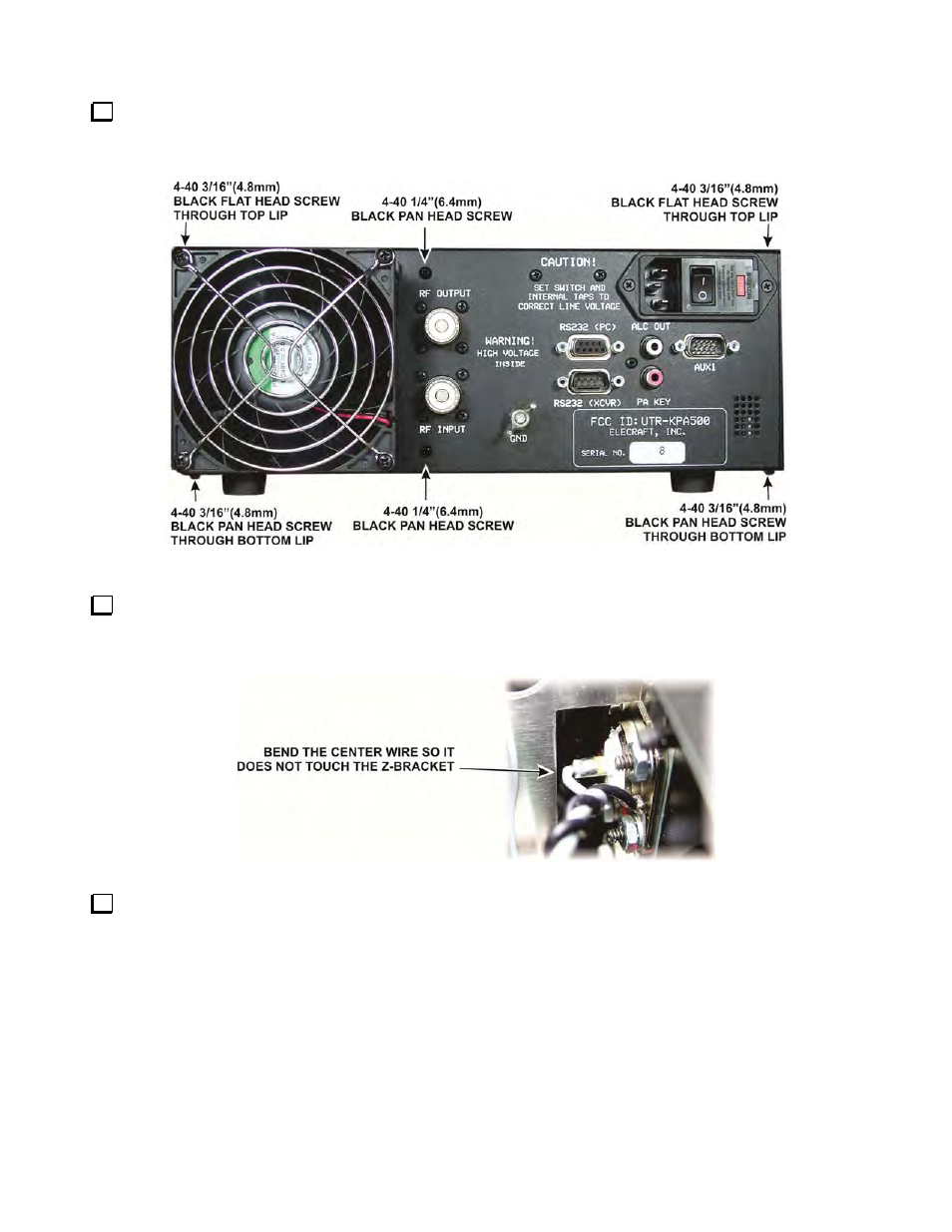
Mount the rear panel assembly on the back of the KPA500 as shown in Figure 39. It may be easier to set the
KPA500 on a side panel so you can adjust the fit on the top and bottom at the same time and get it to clear the
Z-bracket assembly on the bottom. Secure the assembly with six screws as shown.
Figure 39. Mounting the Rear Panel Assembly on the KPA500 Chassis.
Look through the top of the KPA500 and check the clearance of gray wire leading to the center pin of the
RF output connector and the Z-bracket. If necessary, bend the wire at the pin as needed for clearance as shown
in Figure 40. A flat blade screwdriver is an excellent tool to bend the wire.
Figure 40. Checking RF Output Connector Center Pin Wire Clearance.
Check the fan to ensure the RF OUTPUT or RF INPUT cables do not interfere with free motion of the
blades. Adjust the cable positions as needed.
- KX3 Owner's Manual (58 pages)
- KX3 Assembly Manual (47 pages)
- KX3 Assembly Manual Errata (5 pages)
- KX3-2M (30 pages)
- KX3-PCKT (2 pages)
- KX3 Mobile Installation And Operation Guide (17 pages)
- KX3 Guide for Blind Operators (7 pages)
- KX3 Quick Reference (2 pages)
- K3 Programmers Reference (26 pages)
- KX3 Speaker Grille Instructions (9 pages)
- KXFL3 Filter Option (12 pages)
- KXFL3 Filter Option Errata (2 pages)
- KXAT3 (5 pages)
- KXBC3 (13 pages)
- KXPD3 (4 pages)
- Proset Boom Headset (1 page)
- PX3 Owner's Manual (53 pages)
- PX3 Owners Manual Errata (2 pages)
- KXPA100 Manual (55 pages)
- KXPA100 Assembly Manual (27 pages)
- KXPA100 Assembly Errata (1 page)
- KXPA100 Programmers Reference (24 pages)
- KXAT100 Installation Manual (17 pages)
- KX1 Manual (96 pages)
- KXAT1 (12 pages)
- KXPD1 (7 pages)
- KXB30 (8 pages)
- KXB3080 (20 pages)
- K1 (91 pages)
- K1 1.09 F/W (1 page)
- KNB1 Manual (8 pages)
- KAT1 Manual (15 pages)
- KFL1-2 (2 pages)
- KTS1 (1 page)
- KBT1 Manual (8 pages)
- KBT1 Manual Errata (2 pages)
- K1BKLTKT LCD Mod Kit (6 pages)
- K2 Owner's Manual (171 pages)
- K2 Owner's Manual Errata (1 page)
- K2 PLL (4 pages)
- K2ATOBKIT (15 pages)
- K2ATOBKT (2 pages)
- K2 Keying Modification Instructions (4 pages)
- KPA100 Manual (74 pages)
- KPA100 Shield Upgrade (3 pages)