Elecraft KPA500 Kit Assembly Manual User Manual
Page 27
26
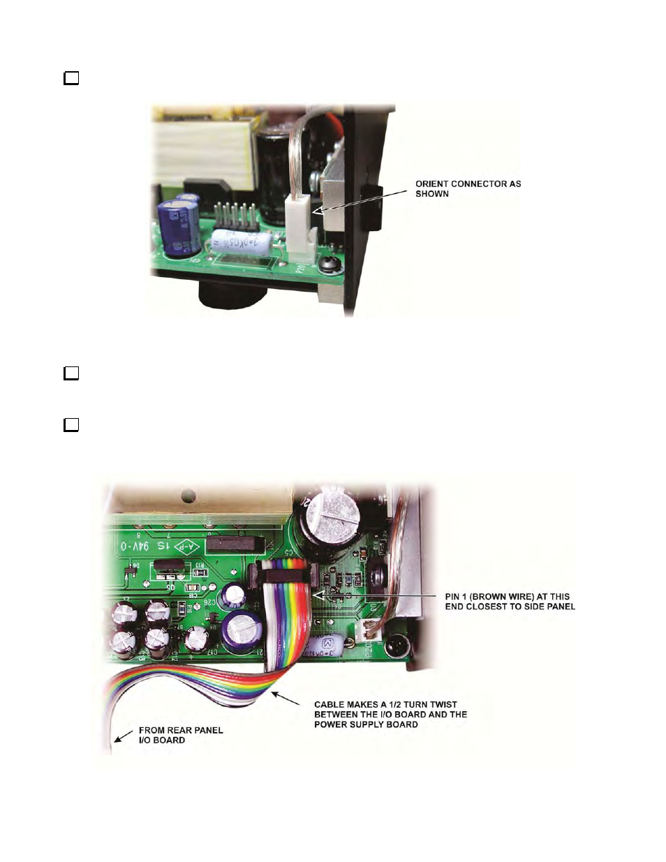
Connect the cable from the interlock switch on the left side panel to the power supply module as shown in
Figure 35.
Figure 35. Connecting the Interlock Cable to the Power Supply Module.
Temporarily route all the heavy wires connected to the power supply module toward the front so they will
be out of the way for the next steps, then place the rear panel assembly directly behind the KPA500 chassis. It
will stand upright, resting on the fan housing.
Connect the 10-wire ribbon cable to the power supply module as shown in Figure 36. Note the brown wire
(pin 1) must go to the end of the connector nearest the KPA500 side panel. To do so it makes a 1/2 turn
twist. Be certain the connector engages both rows of pins.
Figure 36. Connecting the 10-Wire Ribbon Cable to the Power Supply Module.
- KX3 Owner's Manual (58 pages)
- KX3 Assembly Manual (47 pages)
- KX3 Assembly Manual Errata (5 pages)
- KX3-2M (30 pages)
- KX3-PCKT (2 pages)
- KX3 Mobile Installation And Operation Guide (17 pages)
- KX3 Guide for Blind Operators (7 pages)
- KX3 Quick Reference (2 pages)
- K3 Programmers Reference (26 pages)
- KX3 Speaker Grille Instructions (9 pages)
- KXFL3 Filter Option (12 pages)
- KXFL3 Filter Option Errata (2 pages)
- KXAT3 (5 pages)
- KXBC3 (13 pages)
- KXPD3 (4 pages)
- Proset Boom Headset (1 page)
- PX3 Owner's Manual (53 pages)
- PX3 Owners Manual Errata (2 pages)
- KXPA100 Manual (55 pages)
- KXPA100 Assembly Manual (27 pages)
- KXPA100 Assembly Errata (1 page)
- KXPA100 Programmers Reference (24 pages)
- KXAT100 Installation Manual (17 pages)
- KX1 Manual (96 pages)
- KXAT1 (12 pages)
- KXPD1 (7 pages)
- KXB30 (8 pages)
- KXB3080 (20 pages)
- K1 (91 pages)
- K1 1.09 F/W (1 page)
- KNB1 Manual (8 pages)
- KAT1 Manual (15 pages)
- KFL1-2 (2 pages)
- KTS1 (1 page)
- KBT1 Manual (8 pages)
- KBT1 Manual Errata (2 pages)
- K1BKLTKT LCD Mod Kit (6 pages)
- K2 Owner's Manual (171 pages)
- K2 Owner's Manual Errata (1 page)
- K2 PLL (4 pages)
- K2ATOBKIT (15 pages)
- K2ATOBKT (2 pages)
- K2 Keying Modification Instructions (4 pages)
- KPA100 Manual (74 pages)
- KPA100 Shield Upgrade (3 pages)