Elecraft KPA500 Kit Assembly Manual User Manual
Page 13
12
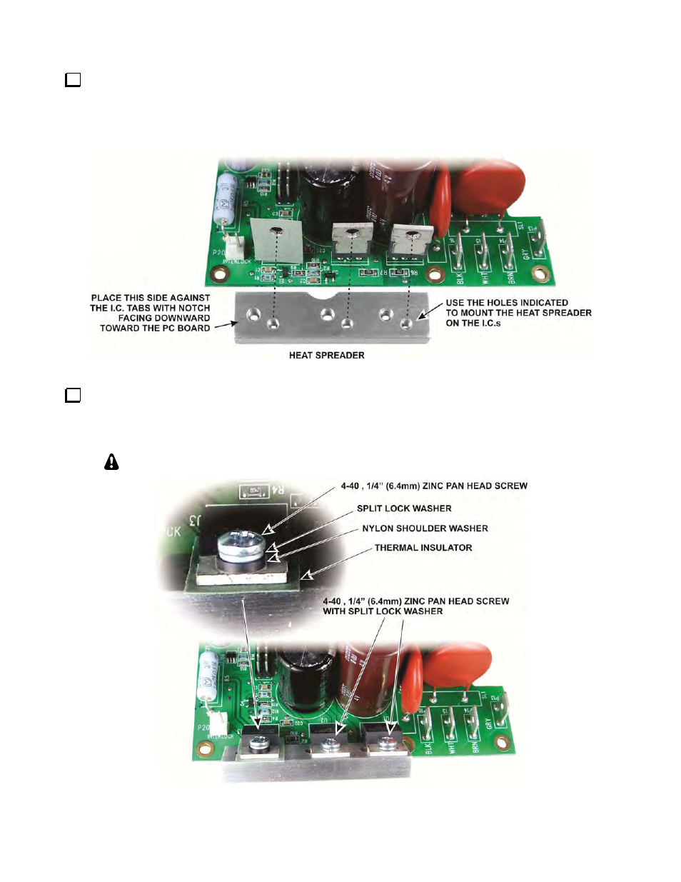
Locate the heat spreader (see Figure 9). Note that it has six threaded holes; three are larger than the others
and the holes are spaced to match the spacing of the I.C.s on the power supply module. The three holes indicated
in the figure will be used to attach the spreader to the I.C.s. The other three holes will be used later to attach the
heat spreader to the KPA500’s enclosure side panel. The spreader must be oriented as shown or the larger
holes will not line up with the holes in the side panel.
Figure 9. Power Supply Module Heat Spreader Orientation.
Attach the heat spreader to the three I.C.s as shown in Figure 10. Bend the I.C. leads as shown to allow you
to use a screwdriver to tighten the screws. Be sure to install the nylon shoulder washer in the hole of U3 (the I.C.
with the thermal insulator) so the screw does not touch any part of the metal tab. Do not over-tighten the screw;
you can crush the shoulder washer.
Do not bend the leads more than necessary or you may break a lead.
Figure 10. Mounting the Heat Spreader on the Power Supply Module.