Elecraft KPA500 Kit Assembly Manual User Manual
Page 24
23
Mount the rectifier board on the Z-bracket as shown in Figure 29. The three holes in the pc board mount on
the three standoffs on the Z-bracket.
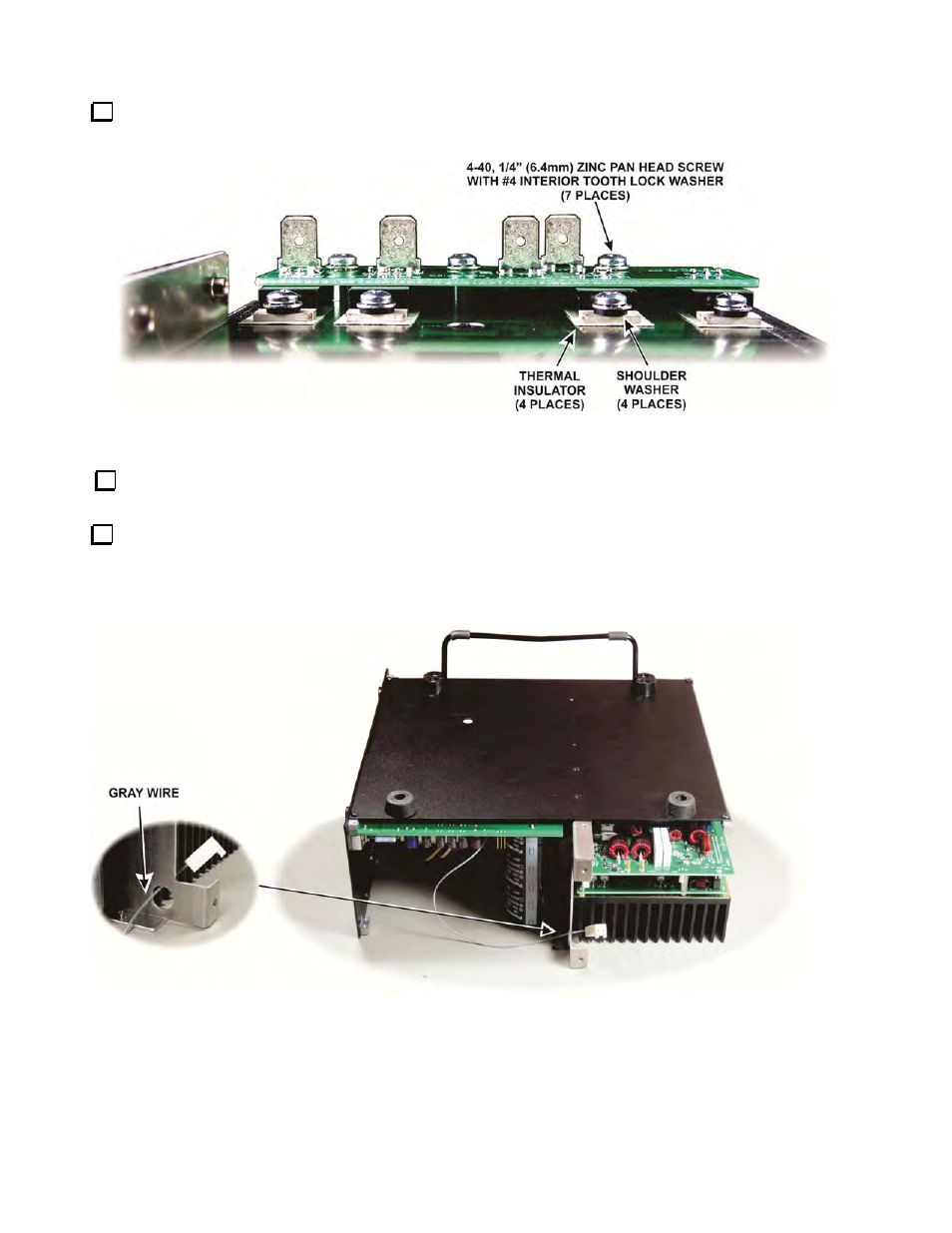
Figure 29. Rectifier Board on the Z-Bracket.
Use your DMM to check for shorts between the metal tab on each rectifier and the bare metal of the Z-
bracket. The DMM should indicate whatever it normally shows when the probes are not touching.
Place the Z-bracket with the rectifier board and PA/LPF module attached on your work table with the heat
sink down, then gently position the bottom cover assembly you completed earlier over it as shown in Figure 30.
Locate and pull the gray wire attached to the power supply module to the rear and route it through the hole in the
Z-bracket as shown. The connector is typically a very tight fit the first time it is passed through the hole.
Figure 30. Preparing to Install the Z-Bracket Assembly in the Bottom Cover.
- KX3 Owner's Manual (58 pages)
- KX3 Assembly Manual (47 pages)
- KX3 Assembly Manual Errata (5 pages)
- KX3-2M (30 pages)
- KX3-PCKT (2 pages)
- KX3 Mobile Installation And Operation Guide (17 pages)
- KX3 Guide for Blind Operators (7 pages)
- KX3 Quick Reference (2 pages)
- K3 Programmers Reference (26 pages)
- KX3 Speaker Grille Instructions (9 pages)
- KXFL3 Filter Option (12 pages)
- KXFL3 Filter Option Errata (2 pages)
- KXAT3 (5 pages)
- KXBC3 (13 pages)
- KXPD3 (4 pages)
- Proset Boom Headset (1 page)
- PX3 Owner's Manual (53 pages)
- PX3 Owners Manual Errata (2 pages)
- KXPA100 Manual (55 pages)
- KXPA100 Assembly Manual (27 pages)
- KXPA100 Assembly Errata (1 page)
- KXPA100 Programmers Reference (24 pages)
- KXAT100 Installation Manual (17 pages)
- KX1 Manual (96 pages)
- KXAT1 (12 pages)
- KXPD1 (7 pages)
- KXB30 (8 pages)
- KXB3080 (20 pages)
- K1 (91 pages)
- K1 1.09 F/W (1 page)
- KNB1 Manual (8 pages)
- KAT1 Manual (15 pages)
- KFL1-2 (2 pages)
- KTS1 (1 page)
- KBT1 Manual (8 pages)
- KBT1 Manual Errata (2 pages)
- K1BKLTKT LCD Mod Kit (6 pages)
- K2 Owner's Manual (171 pages)
- K2 Owner's Manual Errata (1 page)
- K2 PLL (4 pages)
- K2ATOBKIT (15 pages)
- K2ATOBKT (2 pages)
- K2 Keying Modification Instructions (4 pages)
- KPA100 Manual (74 pages)
- KPA100 Shield Upgrade (3 pages)