Interlock switch and left side panel feet – Elecraft KPA500 Kit Assembly Manual User Manual
Page 15
14
Interlock Switch and Left Side Panel Feet
Locate the left side panel and remove any masking tape found on the inside (partially painted) surface.
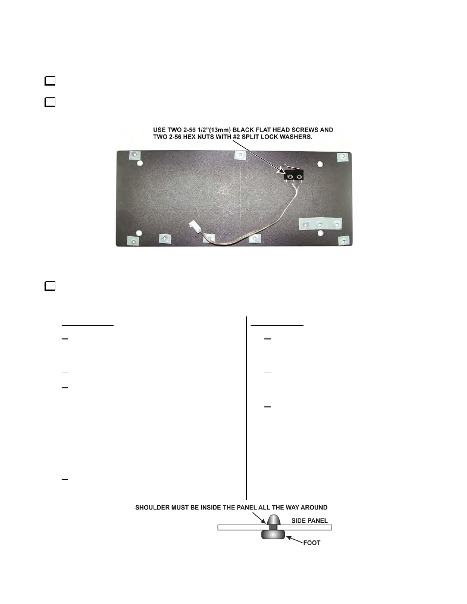
Locate the interlock switch and mount it on the inside (not fully painted) side of the side panel as shown in
Figure 12.
Figure 12. Mounting the Interlock Switch on the Left Side Panel.
Install the four rubber side feet in the large holes in the left side panel. Be sure the large flat side of each
foot is on the outside (fully painted side) of the panel. The feet should be fully seated in the holes as shown in
Figure 13. Two suggested procedures for doing this are as follows:
Press Method:
Wet the tip of the foot with a tiny amount of
soap. (Do not use petroleum jelly or oils. They
can deteriorate the rubber over time).
Place the foot, tip up, on a solid work surface.
Position the panel with the outside (fully painted
side) toward the foot with the hole in the panel
against the tip and press down. The tip should
slip through the hole without further help. If
necessary, grip the tip and pull with your long-
nose pliers, working it from side to side until the
shoulder opens against the inside of the panel.
Do not use excessive force. You can tear the
foot apart.
Wipe any excess soap off of the panel or foot.
Twist Method:
Press the foot against the outside (fully
painted side) of the panel so the tip is in
the hole at an angle.
While pressing the tip into the hole, twist
the foot so the edge of the tip grabs the
inside edge of the hole.
Continue pressing and twisting until the
tip is fully inside the panel all the way
around its circumference. Do not twist
with excessive force. You can tear the
foot apart.
Figure 13. Side Panel Foot Installation.