EFCO 8800 Series Assembly Instructions Vol.5 User Manual
Page 84
EFCO 2009
Page 84
Series 8700 / 8800 Unitized Curtain Wall Assembly Instructions - Volume 5
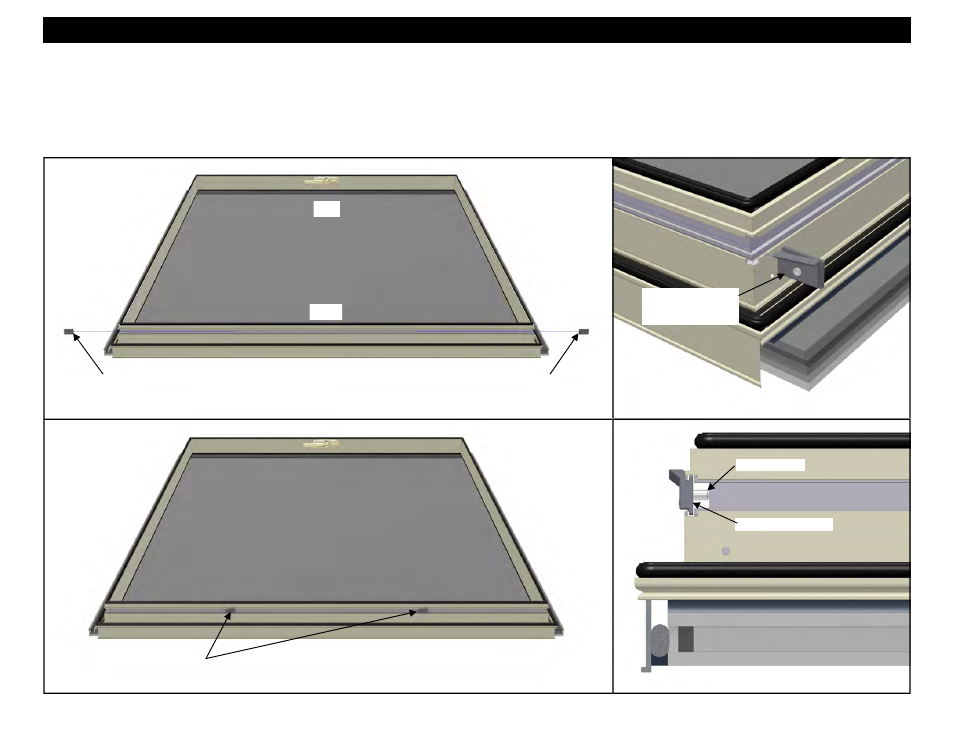
Figure 221
Section 31 - Gasket Application and Hardware Mounting On Vent Frame
Slid each snubber
into the grooves in
the hardware reglet.
Figure 222
Figure 224
14. Measure and mark all centerline locations for the snubbers at the head sash. Refer to the final approved shop drawings and the factory order for locations.
15. Apply the snubbers at the head of the vent opening by sliding each snubber into the grooves in the hardware reglet. See Figure 223. Align the snubbers,
centered on the marked centerline locations and tighten the pinning screw with an Allen wrench. The number and location of snubbers will vary depending
on vent size and design pressure. Snubbers will not be required for all vent configurations. Refer to the final approved shop drawings and the factory order
for quantities and locations. See Figures below.
Adjustable Snubbers
HEAD
SILL
Figure 223
Adjustable Snubber
Adjustable Snubber
HEAD
HEAD
Adjustable Snubber
Pinning Screw