Section 15 - general notes and guidelines – EFCO 8800 Series Assembly Instructions Vol.5 User Manual
Page 5
EFCO 2009
Page 5
Series 8700 / 8800 Unitized Curtain Wall Assembly Instructions - Volume 5
Section 15 - General Notes and Guidelines
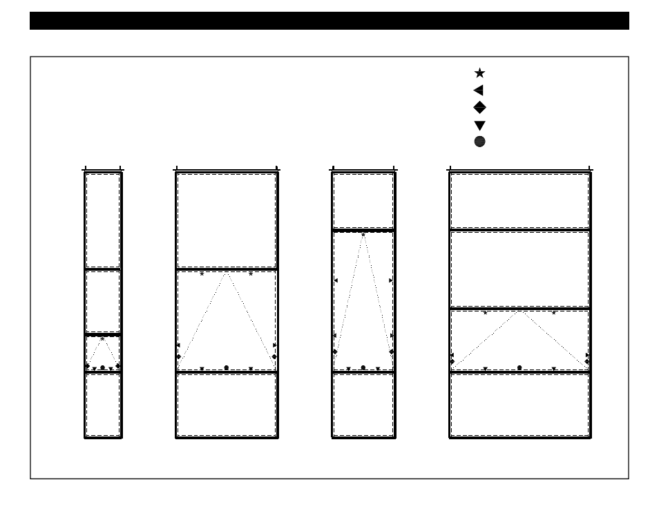
1. Below illustrates the recommended hardware locations for various unit configurations.
2. The exact lock locations and quantities will be determined on a job by job basis and will vary with the design
pressure and vent configuration for a given project. Refer to the final approved shop drawings for quantities and
locations. Snubbers at the vent head may not be required depending on structural loads and the size of the vent.
3. Opening limiting hardware is required for all vent installations. The maximum opening size for vents will be
determined by local code, but may not exceed more than opening at a 20 degree angle normal to the plane of the
wall for safety reasons.
Snubber Locations
Jamb Lock Locations
Limit Arm Locations
Sill Lock Locations
Lock Handle Locations
Typical Hardware Locations