EFCO 8800 Series Assembly Instructions Vol.5 User Manual
Page 33
EFCO 2009
Page 33
Series 8700 / 8800 Unitized Curtain Wall Assembly Instructions - Volume 5
Section 23 - SSG Vent Unit Glazing at Stack Sill : C. Adapter Installation
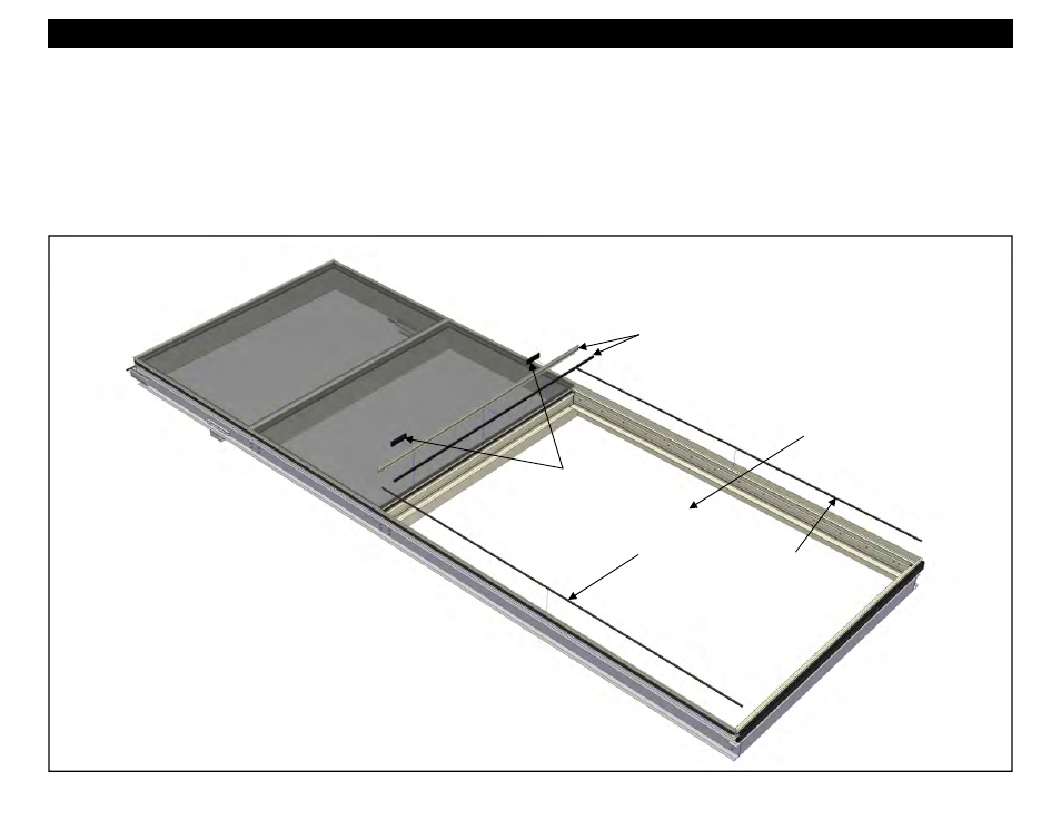
Figure 48
HEAD
SILL
9. Slide the WS00 vent surround gasket into the 17A6 adapters that will be applied to the intermediate horizontals at the head of the concealed vent opening.
Cut the WS00 gasket about 1/4” longer than the 17A6 adapter that will be applied at the head of the vent opening. See Figures 49 through 52 on page 34.
10. Roll the 17A6 adapter into the isolators in the intermediate horizontals at the head and sill of the vent opening. Crowd the WS00 gasket at the head between
the vertical fin bar adapters as the adapter is inserted in place. Center the WS00 gasket in the opening at the sill of the vent opening.
11. Insert HS32 setting blocks between the 17A6 adapter at the head of the vent opening and the upper lite of glazing at quarter points or as directed in the final
approved shop drawings. See Figures 49 through 52 on page 34.
12. Insert WA07 vent bulb gasket into each jamb on each side of the vent opening. Cut the WA07 gasket so that it butts into the 17A6 adapter at the head and sill
of the vent opening. See Figures 49 through 52 on page 34.
Slide WS00 gasket into 17A6 and
apply 17A6 fin bar to the horizontals at
the head and sill of the vent opening.
See Figures 49 - 52 on Page 34.
Insert HS32
setting blocks.
Insert WA07 vent bulb gasket
into each jamb on each side of
the vent opening. See Figures
46 - 52 on page 34.
Concealed Vent
opening