EFCO 8800 Series Assembly Instructions Vol.5 User Manual
Page 75
EFCO 2009
Page 75
Series 8700 / 8800 Unitized Curtain Wall Assembly Instructions - Volume 5
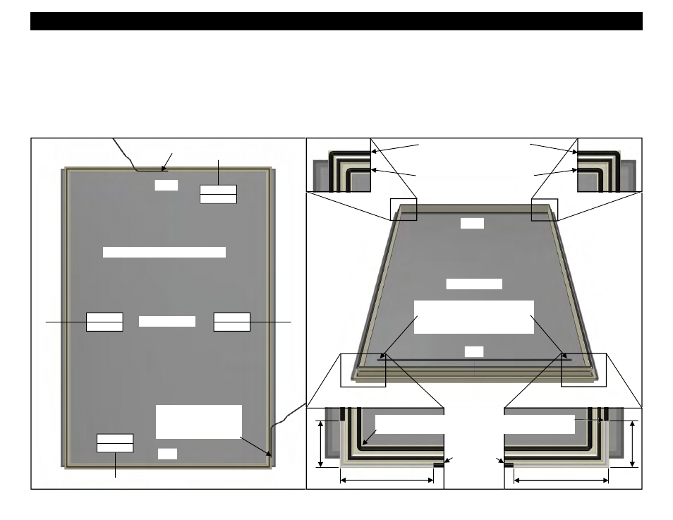
HEAD
SILL
INTERIOR VIEW
Figure 195
Page 77
Figure 196
Page 77
Figure 193
Page 77
Figure 194
Page 77
6”
3”
6”
3”
Apply the interior WA07 preset gasket
starting at the center of the head sash.
INTERIOR VIEW
HEAD
SILL
Exterior WA07 starts and ends 3”
above the sill sash and wraps
around on three sides of the vent.
Apply exterior WA07
preset gasket to the jamb
starting 3” above the sill
sash. (See Figure 192)
Interior WA07 starts at the center of
the head sash and wraps around on
all four sides of the vent.
Interior WA07 wraps around
on all four sides of the vent.
Exterior WA07 wraps around
on three sides of the vent.
Apply a piece of the WA07 preset
gasket to the exterior leg of the sill
sash of the vent that starts and
stops 6” short of the jamb sash.
WA07 Preset
Gasket
Section 31 - Gasket Application and Hardware Mounting On Vent Frame
Figure 191
1. The figures below show a vent configuration for a SSG vent with a fixed horizontal at the vent sill. All other vent configurations will receive the WA07 preset
gasket in the same fashion. See Figures 197 - 200, page 77, 201 - 204, page 78, and 205 - 208, page 79.
2. Apply the interior WA07 preset gasket starting at the center of the head sash. The interior WA07 gasket wraps around on all four sides of the vent with one
continuous piece. Form as tight a radius as possible at the corners with the gasket. Ensure the gasket is not stretched during application. Butt the ends
together at the head, crowding in extra gasket to ovoid gaps later due to gasket shrinkage. See the Figures below and 194 - 196 on page 76.
3. Apply the exterior WA07 preset gasket to the jamb starting and ending 3” above the sill sash wrapping around the corners at the head. The exterior WA07
wraps around both jambs and the head on only three sides of the vent as one continuous piece. (See Figure 192).
4. Apply a piece of the WA07 preset gasket to the exterior leg of the sill sash of the vent that starts and stops 6” short of the jamb sash. See Figure 192 below.
Figure 192
SSG Vent at Fixed Horizontal