EFCO 8800 Series Assembly Instructions Vol.5 User Manual
Page 49
EFCO 2009
Page 49
Series 8700 / 8800 Unitized Curtain Wall Assembly Instructions - Volume 5
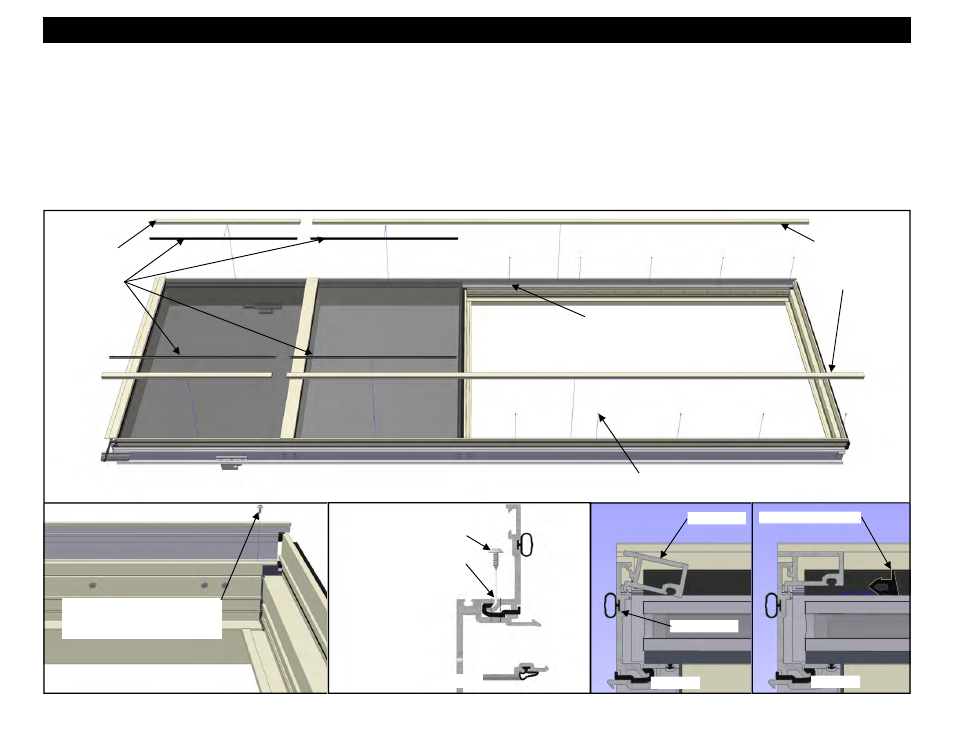
12. Drill tap sized holes (.113 diameter or #33 drill) in the face of the vertical assemblies, 1” from the sill end of the vent opening, and 18” on center to the top of
the vent opening. See figure 82 below. Drill the holes in the groove formed where the adapter meets the mullion. The holes should penetrate the adapter,
the isolator, and the first wall of the mullion where the isolator is seated. See Figure 82 below. Ensure the adapter is properly positioned and seated into the
isolator before drilling.
13. Apply STC6 fasteners in each hole to retain the adapters where they span the vent opening. See Figures 80 and 81.
14. Insert 17A3 cover into 17A2 captured glazing adapter at each unit jamb and rotate into place as shown in Figures 83 and 84.
15. Cut the WC22 gaskets approximately 2” longer than the D.L.O. dimension.
16. Drive in WC22 wedge gaskets as shown in Figure 84. The gaskets should be applied starting in the center of the D.L.O., and then working from the ends,
work the gaskets in place to the center of the lite.
Section 25 - Captured Vent Unit Glazing at Stack Sill : C. Adapter Installation
Figure 80
HEAD
SILL
Insert 17A3 covers
into 17A2 captured
glazing adapters
and drive in wedge
gaskets.
17A3 Covers
17A3 Cover
WC22 Wedge Gasket
17A2 Adapter
Figure 83
Figure 84
WC22 Wedge
Gaskets
Drill tap sized holes in the face of the
vertical assembly 1” from the sill end
of the vent opening, and 18” on
center to the top of the vent opening.
Apply STC6 fasteners in each hole to retain the
adapters where they span the vent opening.
Figure 82
Figure 81
Drill tap sized holes in the
groove formed where the
adapter meets the mullion.
Apply STC6 fasteners in each
hole to retain the adapters where
they span the vent opening.
STC6 18” o/c