Section 30 - hardware mounting on unit frame – EFCO 8800 Series Assembly Instructions Vol.5 User Manual
Page 73
EFCO 2009
Page 73
Series 8700 / 8800 Unitized Curtain Wall Assembly Instructions - Volume 5
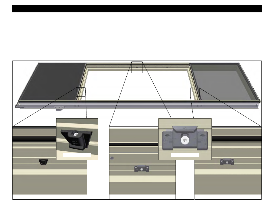
Figure 181
Section 30 - Hardware Mounting On Unit Frame
1. Measure and mark all centerline locations for the keeps and the snubbers. Refer to the final approved shop drawings and the factory order for locations.
2. Apply the snubbers at the head of the vent opening by inserting the tab of each snubber into the groove in the hardware reglet of the horizontal and rotate
into position. Align the snubbers, centered on the marked centerline locations and tighten the pinning screw with an Allen wrench. The number and location
of snubbers will vary depending on vent size and design pressure. Snubbers will not be required for all vent configurations. Refer to the final approved shop
drawings and the factory order for quantities and locations. See Figures 182 below, and 185-187 on page 74.
3. Apply the keepers at the jambs and sill of the vent opening by inserting the tab of each keeper into the groove in the hardware reglet of the jamb adapters
and the sill and rotate into position. Align the keepers, centered on the marked centerline locations and tighten the pinning screw with an Allen wrench. The
number and location of keepers will vary depending on vent size and design pressure. Keepers will not be required at the jambs for all vent configurations.
Refer to the final approved shop drawings and the factory order for quantities and locations. See Figures 183 and 184 below, and 188-189 on page 74.
HEAD
SILL
Figure 182
Figure 183
Figure 184
Adjustable Snubbers
Adjustable Keepers
Adjustable Keepers
Adjustable Keeper
Adjustable Snubber