EFCO 8800 Series Assembly Instructions Vol.5 User Manual
Page 80
EFCO 2009
Page 80
Series 8700 / 8800 Unitized Curtain Wall Assembly Instructions - Volume 5
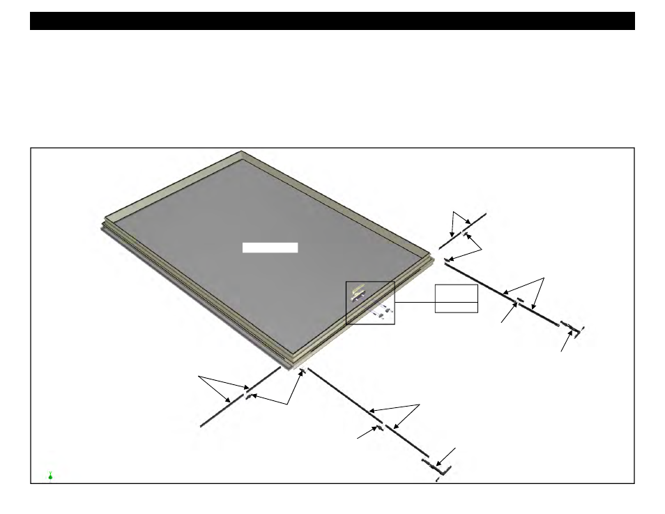
Section 31 - Gasket Application and Hardware Mounting On Vent Frame
Figure 209
5. Install the lock handle to the sill of the vent. Insert the lock handle connection block bars into the slot in the sill, aligning it with the mounting holes. Attach it
with the (2) supplied fasteners. Ensure the lock handle is properly installed so that when the handle is operated, it rotates away from the glazing. Left or right
hand lock handles are available. Refer to the approved shop drawings and the factory order for the required handing. See figures 210 and 211 on page 81.
6. Slide the connection blocks onto the connection block bars of the lock handle positioned as shown in Figure 212 on page 81.
7. Slide the (2) linkage struts and lock pawls on each side of the lock handle into the hardware reglet in the sill. As the first strut is slid into position, slide in the
adjacent lock pawl at the same time. Insert the stud on the lock pawl into the hole in the end of the strut and slide the pawl half way into the reglet. See
Figure 213 on page 81. Insert the stud on the other end of the lock pawl into the hole in the end of the second strut and slide the pawl and the second strut
into the reglet until the hole at the end of the first strut aligns with the hole in the connection block at the lock handle. See Figure 214 on page 81. Attach the
strut to the connection block with the supplied fasteners. Repeat the steps above for the struts and lock pawl on the opposite side of the lock handle.
HEAD
SILL
Figures 210,
211, 212
Page 81
Sill Linkage
Struts
Jamb Linkage
Struts
Sill Linkage
Struts
Jamb Linkage
Struts
Lock Pawls
Lock Pawl
Lock Pawl
Lock Pawls
Corner Drive
Corner Drive
INTERIOR VIEW