Dave Smith Instruments PRO 2 User Manual
Page 35
25
Pro 2 Operation Manual
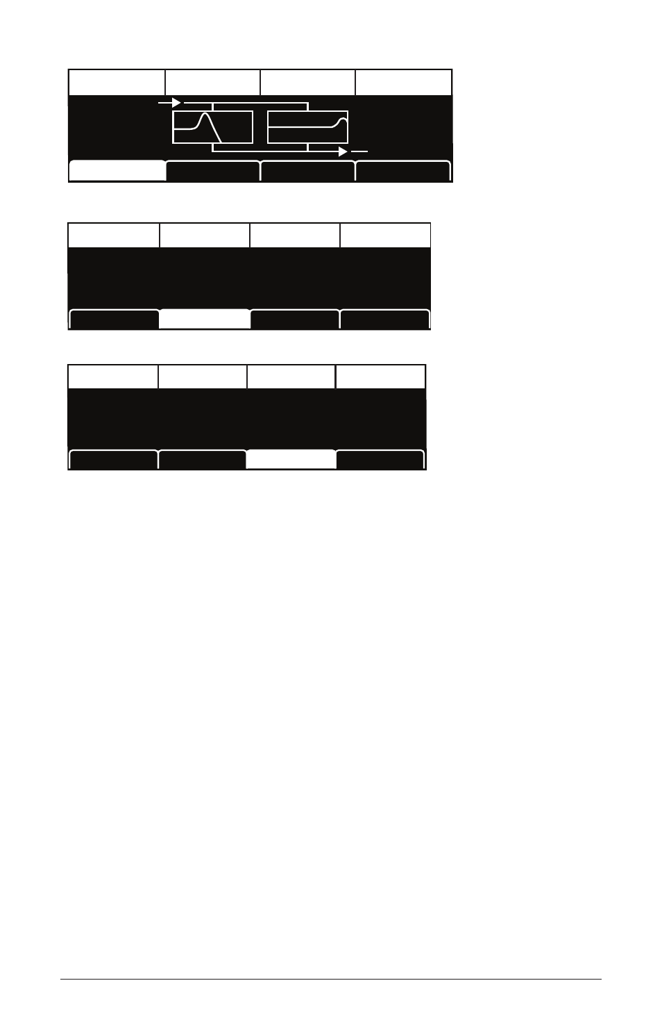
Filter 1 & 2
LP <-> HP
Ser/Par Mix
Filter Route
Notch/BP
Filter 1
Filter Route
Freq: 34
Res: 89
Freq: 164
Res: 41
N/BP: 0
LP/HP: 0
Filter 2
KEY> F1 Freq
F1 Freq
Resonance
Boost
Filter 1
Filter Route
Filter 2
O
RESONANCE
120
F1 FREQ
0
BOOST
0
KEY > F1 FREQ
Key> F2 Freq
F2 Freq
Resonance
LP <-> HP
Filter 1
Filter Route
Filter 2
41
RESONANCE
120
F2 FREQ
0
LP <-> HP
0
KEY > F2 FREQ
Enable
—Enables the chosen filter. Pressing both buttons at the same
time enables both filters. When both are enabled, the
filter
routing
knob
allows you to choose whether the filters operate in series, in parallel, or a
variable mix of both.
Link FIlters
—When enabled, adjusting the font-panel
frequency
or
reSonance
controls of either filter will apply the settings to both. This
button also links both filter envelopes and their amounts.
Frequency: 0...164
—Sets the filter’s cutoff frequency. On Filter 1,
frequencies below the cutoff pass through unaffected, hence the name
“low-pass.” On Filter 2, the cutoff frequency operates as follows:
• Low-pass: passes frequencies below the cutoff frequency
• Notch: removes frequencies in a notch centered around the cutoff
frequency.
• High-pass: passes frequencies above the cutoff frequency
• Bandpass: passes a band of frequencies centered around the cutoff
frequency