Warning, Operating your furnace, Electric power supply – Qmark CFWF - Counterflow Electric Wall Furnace User Manual
Page 8: Junction box, Electrical connection, Grounding, Low voltage connections, Figure 11
Electric Power Supply
Your Counterflow Wall Furnace requires a 240-volt, 60
cycle, 40-ampere circuit from a separate circuit breaker or
fuse in your service panel. Do not run supply wires inside
the furnace cabinet, except from the top of the cabinet
down to the junction box.
Junction Box
Power supply connections are made inside the junction
box located in the upper end of the cabinet. See Fig. 11
and Fig. 1, page 2.
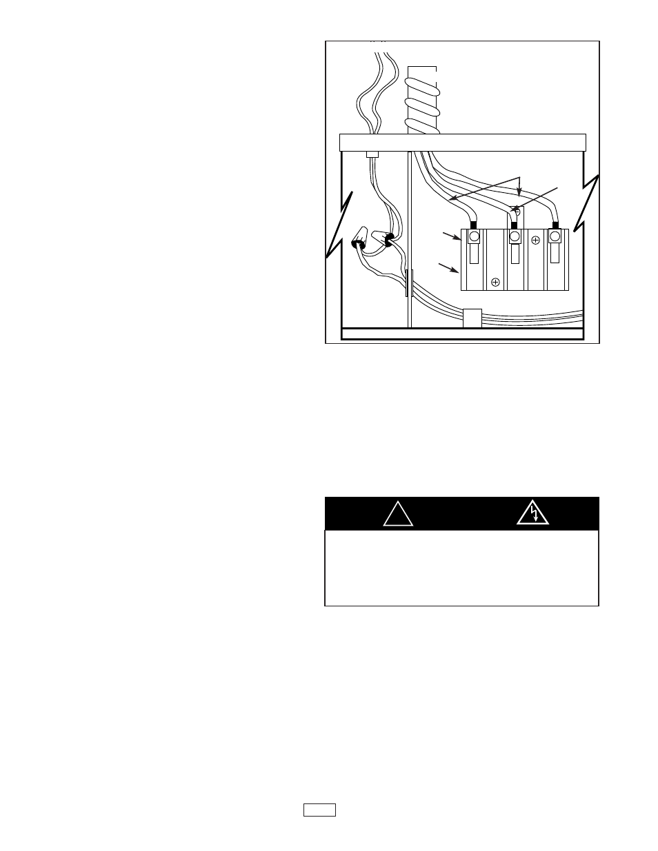
Electrical Connection
Connect 240V conduit to top of furnace as shown in Fig.
11. Pull supply wires through conduit and into junction
box. Attach 240V supply wires to "LINE" connection at
terminal board. Refer to wiring diagram on junction box
cover plate. If you do not feel comfortable doing this, or
have any doubts
how to comply with code, consult your electrical inspector
or a licensed electrician.
Grounding
Provide ground connection from the unitʼs terminal board
to a grounded connection in the electrical service panel or
a properly driven and electrically grounded ground rod.
Low Voltage Connections
Run thermostat wire to the furnace. See THERMOSTAT
INSTALLATION, page 6.
Connect the thermostat wires to the two (thermostat)
wires extending inside the junction box. Refer to wiring
diagram on junction box cover plate and Fig. 11.
When furnace mounting has been completed, see steps
1, 2, and 3 below.
Refer to Fig. 1, page 2.
1. Replace junction box cover plate. Tighten screws
securely.
2. Replace bottom front panel
3. Replace top front panel.
Note: For supply connections use 6 AWG or larger wires
suitable for at least 60 C (140 F). Use copper wire only.
Operating Your Furnace
This heater is controlled by a 24-volt wall thermostat that
is included. Set the thermostat to a higher temperature
than you think will be comfortable. Let the heater run and
when the room reaches a comfortable temperature, adjust
the dial counter-clockwise slowly until the heater cuts off.
The thermostat will maintain this temperature.
This heater is equipped with an automatic reset over-tem-
perature device. This device cuts the heater off if it should
operate at an abnormal temperature. Also, a pilot light
located on the top right of the fan panel (visible through
the grille) will come on. When the heater cools back down
to a normal level, the automatic reset will restore opera-
tion and the pilot light will turn off.
Additionally, your heater is equipped with micro temp heat
limits ("one-shots") to protect against excessive and pro-
longed current surges. If these device(s) open(s) the
heating circuit, the limit(s) must be replaced by a qualified
Service Technician, who will also determine and correct
the cause of failure.
Air volume may be adjusted if you have installed the
CFWFRO rear grille. Do not attempt to reduce the flow
of air from the front grille. Doing so will cause the limit
devices to shut down the heater. Do not obstruct the front
grille (or rear grille, if so equipped).
TO THERMOSTAT
CONDUIT
ELECTRICAL SUPPLY
WIRES-240V
SEE WIRE
CONNECTION
DIAGRAM
ABOVE
TO APPROVED
GROUND
TERMINAL
BOARD
LINE 1
GND.
LINE 2
JUNCTION
BOX
Figure 11
NOTE: ALL WIRING NOT SHOWN
8
If this light comes on this means your
heater has operated abnormally. Check for
air blockages and remove. If this does not
solve your problem, call a qualified
Service Technician.
WARNING
!