Cut wall openings, Electrical supply rough-in, Figure 3 figure 4 – Qmark CFWF - Counterflow Electric Wall Furnace User Manual
Page 4: Figure 5
Note: IF STUDS ARE NOT ON 16-INCH (406 mm) CEN-
TERS, SEE CLOSE OFF STUD SPACE ON PAGE 4 AND
5.
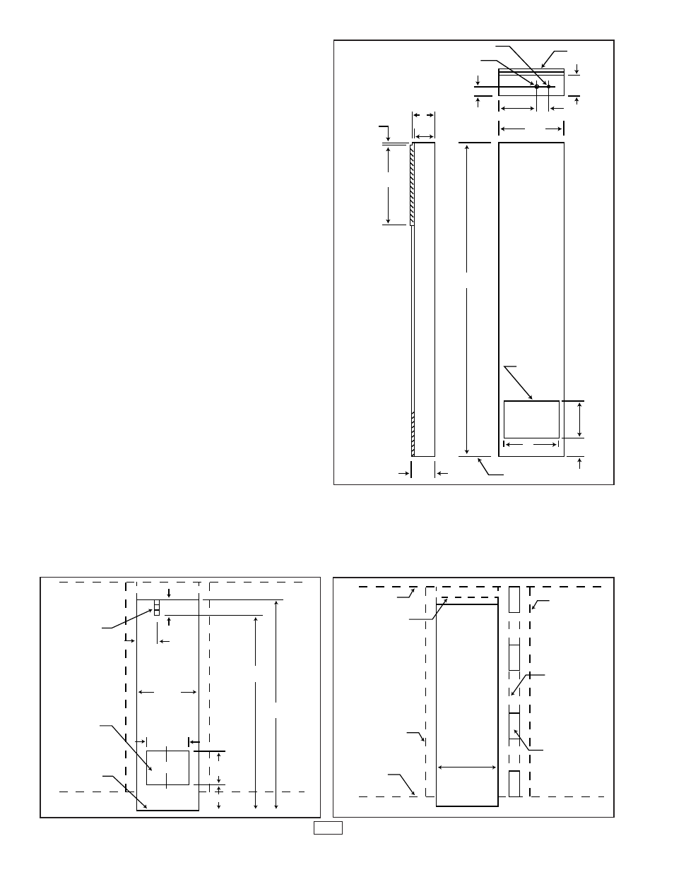
Cut Wall Openings
Refer to Figure 3. Lay out and cut the required opening
in wall.
The vertical height given includes an allowance of 3 inch-
es (76 mm) extra to allow room for wiring after the furnace
is installed.
Electrical Supply Rough-In
1. Make entry holes in the ceiling wall plate above the fur-
nace to route the conduit, electrical power supply
wires, and the thermostat wiring to the furnace.
2. If this is impractical, entry holes 1 inch (25 mm) for
electrical conduit and 1/2 inch (13 mm) for thermostat
wire may be drilled through either wall stud above the
furnace and the wiring may be routed from an adjoin-
ing stud space. You may also route the wiring from the
crawl space or basement to a point above the furnace
to match the openings in Fig. 4.
3. Install conduit so that it extends 4 inches (102 mm)
below the top of the furnace wall opening. One (1)
inch (25 mm) of conduit should extend inside the fur-
nace cabinet (See Fig. 3).
Note: Flexible conduit may be used only if it meets local
codes and ordinances.
1. The electrical supply wires, ground wire, and the ther-
mostat wires may now be routed to the furnace loca-
tions. See THERMOSTAT INSTALLATION, pages 6,
and ELECTRICAL WIRING page 8.
2. Ensure that there is enough wire at the furnace to
make the connections inside the furnace junction box.
Close Off Stud Space (If Necessary)
If studs are not on 16 inch (406 mm) centers, cut the hole
for the Counterflow Wall Furnace next to an existing stud
and frame in the other side using a 2x4 (or other lumber
as required) and spacer blocks or shims. See Fig. 5.
CL
Figure 3
Figure 4
FLEXIBLE
CONDUIT
FINISHED
FLOOR
6”
4”
14-3/8”
(365mm)
12-1/4”
(311mm)
71-1/2”
(1816mm)
75-1/2”
(1905mm)
8-1/4”
(210mm)
3-3/4”(95mm)
WALL CUTOUT
FOR OPTIONAL
REAR OUTLET
CENTERED
BETWEEN STUDS
12”
8”
(203mm)
4-7/8”
OPTIONAL REAR
OUTLET CUTOUT
MARKS
FINISHED FLOOR
6-5/8”
168 mm
72-1/2”
(184cm)
BACK
FRONT
SIDE
14-1/8”
7”
6-1/8”(156mm)
24V THERMOSTAT WIRE ENTRY
3/4” (19 mm) CONDUIT ENTRY
FRONT
1/2”
18-3/8”
(467mm)
2”
8”
2-1/4” (57mm)
6-1/8”
(156 mm)
(203mm)
(50 mm)
(359mm)
(13mm)
(305 mm)
(124 mm)
(102mm)
(152mm)
4
Figure 5
CEILING
PLATE
2X4 BACKING
IF MORE THAN
18” BETWEEN
TOP OF
CUTOUT &
CEILING LATE
EXISTING STUD
FLOOR PLATE
14-3/8”
(365mm)
SPACER
BLOCK AS
REQUIRED
NEW STUD
EXISTING STUD
(179mm)