Cfwf920 description, Removing your furnace from the carton, Optional accessories – Qmark CFWF - Counterflow Electric Wall Furnace User Manual
Page 2
CFWF920 Description
Your Counterflow Wall Furnace is shipped assembled for
installation on any wall. It may be recessed up to 5-3/8
inches (137 mm) with studs spaced 16 inches (406 mm)
on center, or it may be mounted directly on the wall sur-
face.
This heater works by drawing cool air in at the top grille
inlet and pushing it with a fan downward over the heating
element. Warm air is discharged into the room through
the bottom grille outlet near the floor. The warm air at the
floor creates a gentle convective process in the room,
preventing stratification of warm air near the ceiling and
ensuring comfort for the occupants.
This heater runs on single-phase 240V line voltage and
produces 9.2 kW of heat or 31,395 BTU/Hr.
The Counterflow Wall Furnace is controlled by a low volt-
age wall-mounted thermostat (provided). The unit is
made of heavy gauge steel with a durable baked powder
coat finish.
Removing your Furnace
from the Carton
T
he shipping carton contains the heater and the parts
needed for installation.
1. While the heater is still in the carton, lift straight up on
the top of the furnace. Remove the top trim cover with
its packing materials and the hardware kit (thermostat,
wire, and screws). Put this hardware kit aside where it
will not be lost or damaged.
2. Finish removing heater from the carton and lay on its
back. Carefully remove the remaining packing sup-
ports from around the furnace and set aside.
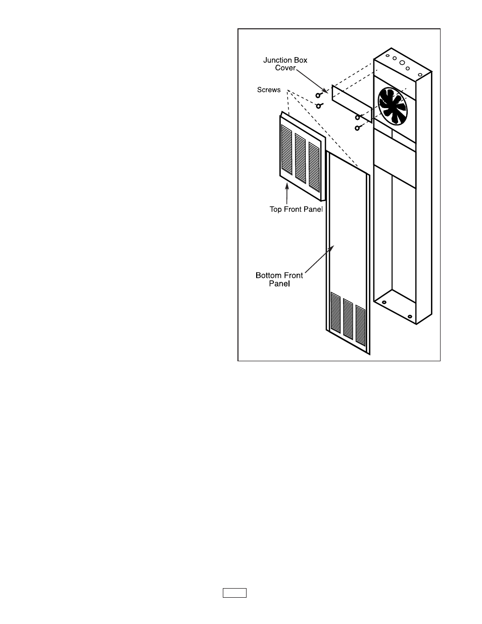
3. Remove the screws from the top front panel. Gently
pull panel toward the top of the cabinet about 1/2 inch
(13 mm). Panel will loosen. Remove panel from cab-
inet and set top front panel and screws aside where
they will not be lost or damaged.
4. Give fan blade a small push counterclockwise to
ensure that it spins freely.
5. Remove the four screws holding the junction box cover
above the fan. Place cover and screws aside where
they cannot be lost or damaged. The electrical junction
box and transformer should now be accessible. Refer
to the section "ELECTRICAL WIRING" before attempt-
ing to wire your heater.
6. Remove the four mounting screws from the bottom
front panel. Remove panel from cabinet. Set panel
and screws aside where they will not be lost or dam-
aged.
7. Before discarding packing material, examine it careful-
ly for any loose furnace parts. Dispose of packing
material properly (recycle).
Optional Accessories
Rear Outlet Kit CFWFRO
This accessory allows you to divert some heated air to a
second room behind the furnace. The finished wall of this
room must be within 10 inches (254 mm) of the furnace.
The built-in damper allows you to close the rear outlet, re-
diverting all the air to the front outlet grill. If this accesso-
ry is to be used, the opening must be cut in the rear of the
cabinet, at this time.
See “Optional Rear Outlet
Installation” section of this manual.
Figure 1
2