Surface mount installation, Thermostat installation, Caution – Qmark CFWF - Counterflow Electric Wall Furnace User Manual
Page 5
In some high ceilings the distance from the top of the
cutout to the ceiling wall plate may be more than 18 inch-
es (457 mm). If so, we recommend that you close off this
space. Nail a 2x4 horizontally between the studs to close
off this space. Drill entry holes in this as required.
Surface Mount Installation
If you are using the optional rear outlet (CFWFRO), refer
to Optional Rear Outlet Installation on page 7 before pro-
ceeding.
Locate Wall Studs
Use a stud locator or small finishing nails. Drive and
remove a small finishing nail through the wall surface until
you find a stud. Then locate the side of the stud using the
same technique. Leaving that locating nail there, locate
the other side of the stud. Once you have done this, you
should be able to easily locate the next stud. The inside
edge of the next stud should be approximately 14-1/2
inches (368 mm) from the one you just found.
Cut Wall Opening
If you are using the optional rear outlet (CFWFRO), cut
the 8-1/4 (210 mm) inch by 12-1/4 inch (311 mm) opening
ONLY as shown in Fig. 3, page 4. Refer to Optional Rear
Outlet Installation on page 7 before proceeding.
1. If impractical to route the wiring to the furnace from the
attic, entry holes 1 inch (25 mm) for electrical conduit
and 1/2 inch (13 mm) for thermostat wire may be
drilled through either wall stud above the furnace and
the wiring may be routed from an adjoining stud space.
You may also route the wiring from the crawl space or
basement to a point above the furnace to match the
openings in Fig. 4.
2. To route the conduit, electrical power supply wires, and
thermostat wires to the furnace top, entry holes must
be made in the wallboard above the furnace location.
3. Electrical supply opening must be located at 2 inches
(51 mm)above the furnace top to match opening
shown in Fig. 4., page 6.
4. Drill a 1-inch (25 mm) hole for the electrical supply
wiring and a 1/2 inch (13 mm) hole for the thermostat
wires at the selected locations.
5. Route the flexible conduit to the 1 inch (25 mm) hole in
the wallboard and allow 1 inch (25 mm) to extend
below the furnace top (71-1/2 inches [1816 mm] from
the finished floor). See Fig. 3, page 4.
6. You may now route the electrical supply wires, ground
wire, and the thermostat wires to the furnace locations.
See THERMOSTAT INSTALLATION, pages 6, and
ELECTRICAL WIRING page 9.
Thermostat Installation
1. Thermostat cable must be run to the location selected.
All wiring must agree with the local codes and ordi-
nances. These instructions describe how to wire the
thermostat from the attic but it can also come from the
basement or crawl space.
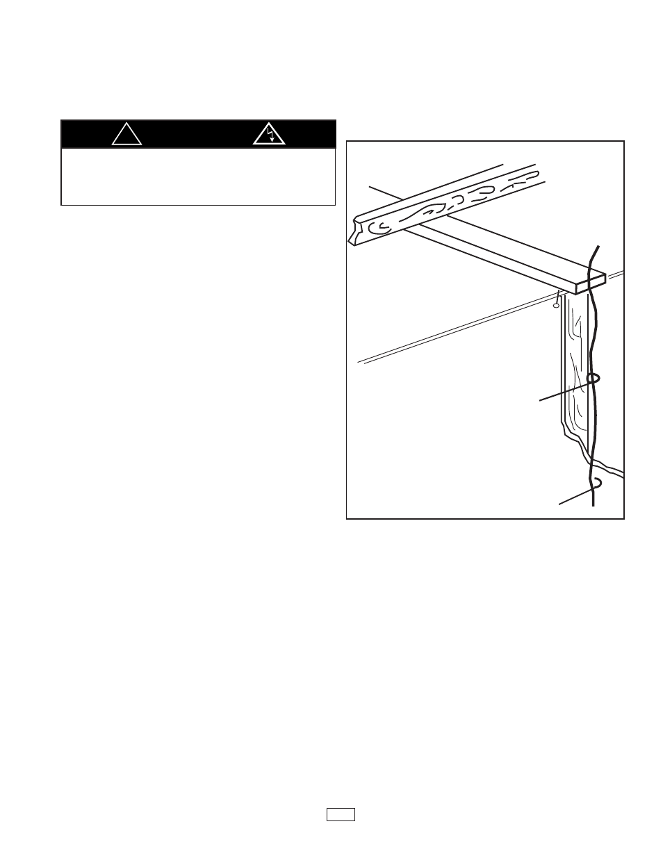
2. Locate the thermostat and then drive a small nail hole
through the ceiling in the corner of the wall and ceiling
above the thermostat location. Pull out the nail and
push a small stiff wire through the hole to locate the
wire in the attic. Drill a 1/2 inch (13 mm) hole through
the ceiling wall plate.
3. Using the stiff wire, probe for obstructions in the wall.
Then drill 1/2 inch (13 mm) hole through the wall at the
selected location for the thermostat.
4. Feed the thermostat cable from the ceiling into the
wall. Snag the thermostat cable through the hole and
pull through so that 6 inches (152 mm) of cable pro-
trudes.
5. Route cable to Counterflow Wall Furnace.
CAUTION
!
To avoid electrical shock, turn off electrical
circuits that run through the wall where you
are installing the furnace.
Route Thermostat Cable
SMALL
FINISH
NAIL TO
LOCATE
HEADER
THERMOSTAT
CABLE
STIFF WIRE TO
SNAG CABLE
5
Figure 6