Warning, Caution, Optional rear outlet installation – Qmark CFWF - Counterflow Electric Wall Furnace User Manual
Page 7: Surface mount furnace
Optional Rear Outlet Installation
Recessed Mount Furnace
1. Cut 8-1/4 inch (210 mm) x 12-1/4 (311 mm) inch hole
in wall as shown in Fig. 3, page 4.
2. There are four diamond-shaped holes at the bottom of
the cabinet on the rear panel. Using these diamond-
shaped holes, draw straight lines to mark your outline
for the CFWFRO and cut out your opening.
3. Mount furnace in the recess. (See Mounting Your
Furnace, Page 3).
4. Place plaster ground in opening and nail into studs.
(Fig. 8)
Note: In new construction, install plaster ground before
wall finish is applied. In drywall construction the plas-
ter ground may be omitted.
5. Center grille over hole in rear wall and mark location
of holes in grille on wall.
6. With a 1/8 inch drill bit, drill (2) holes through plaster
or drywall and the cabinet for attaching grille.
7. Attach the grille with screws provided (Fig.10). The 10
inch boot is not required for recessed installation.
Surface Mount Furnace
1. Cut 8-1/4 inch (210 mm) x 12-1/4 inch (311 mm) hole
in wall as shown in Fig. 3, page 4.
2. There are four diamond-shaped holes at the bottom
of the cabinet on the rear panel. Using these dia-
mond-shaped holes, draw straight lines to mark your
outline for the CFWFRO and cut out your opening.
3. Place the boot against cabinet with inner side of boot
exactly on the edges of the hole.
4. Mark screw locations, remove boot and drill holes for
sheet metal screws.
5. Attach boot to back of furnace with screws provided.
6. Place plaster ground in opening and nail into studs
(Fig. 8).
Note: In new construction, install plaster ground before
wall finish is applied.
7. Place furnace with boot attached through hole in wall
and mark end of the boot so it can be cut off flush with
the outer wall.
8. Remove furnace from wall and cut boot where
marked.
9. Place furnace with trimmed boot attached, through
holes in wall and mount the furnace. (See Mounting
Your Furnace, page 6).
10. Center grille over hole in rear wall and mark location
of holes in grille on wall.
11. With a 1/8 inch drill bit, drill (2) holes through plaster
ground and plaster (or drywall).
12. Attach grille with screws provided (Fig. 10).
TURN OFF ELECTRIC POWER AT
FUSE BOX OR SERVICE PANEL
BEFORE MAKING ANY ELECTRICAL
CONNECTIONS.
INSULATE WHERE NECESSARY...
ALL LINE VOLTAGE AND GROUND CON-
NECTIONS MUST BE COMPLETED BEFORE
ELECTRICAL POWER IS RESTORED.
All electrical work must conform to your
local codes and ordinances and with the
National Electrical Codes.
7
WARNING
!
yyy
yyy
yyy
yyy
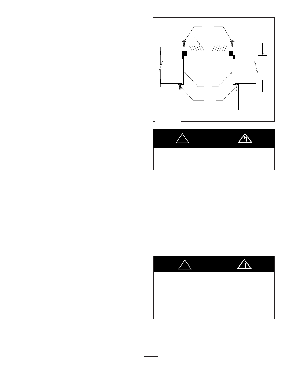
Figure 10
SCREWS
GRILLE
1/2”
TO
10”
BOOT
SCREWS
SURFACE MOUNTING
(BOOT TRIMMED FLUSH WITH WALL)
CAUTION
!
Label all wires prior to disconnection
when servicing. Wiring errors can
cause improper and dangerous
operation. Verify proper operation
after servicing.
Danger of Property Damage,
Bodily Injury, or Death