Dell Inspiron 7500 User Manual
Page 83
Back to Contents Page
Palmrest Assembly and Palmrest Assembly Component Removal: Dell™ Inspiron™
7500
To remove the internal modem card, follow these steps:
1. Gently pull the modem card off of connector JP19 on the system board. Do not rock the card to remove it, because this may damage the
connectors.
2. Remove the carrier tray by sliding it toward the back of the computer.
3. Remove the modem card from the carrier tray.
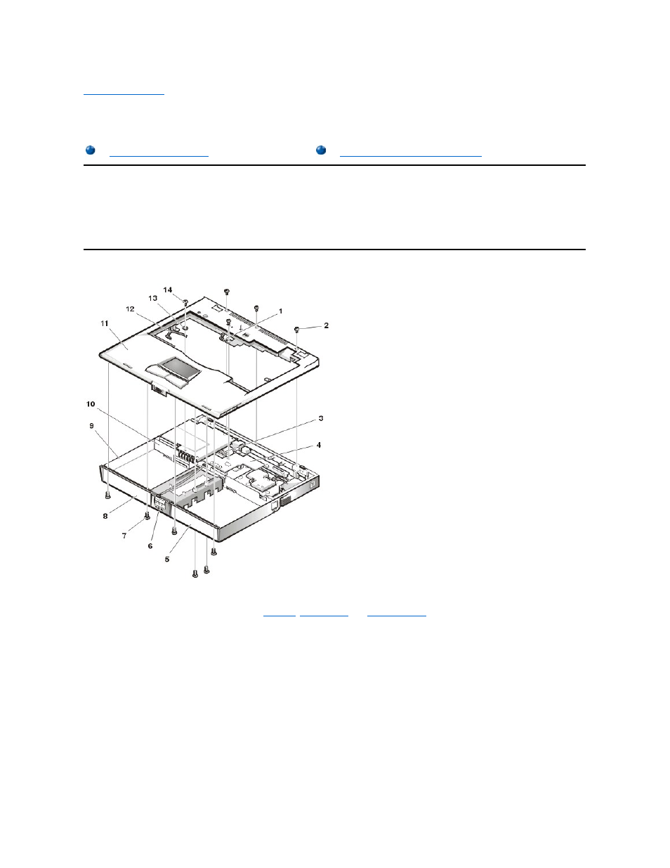
Palmrest Assembly Removal
This procedure assumes that you have removed the
keyboard
,
thermal shield
, and
display assembly
. To remove the palmrest assembly, follow
these steps:
1. Turn the unit over and place it face down.
2. Remove the (2) 4-mm screws from the top inside of the combo bay.
3. Remove the (2) 4-mm screws from the top inside of the MegaBay.
4. Remove the (2) 4-mm screws from the top inside of the hard-disk drive bay.
5. Turn the unit back over.
6. Remove the (3) 6-mm screws from the top of the base assembly, along the back edge.
7. Remove the 6-mm screw from the DC-DC board.
8. Remove the 4-mm screw and the washer securing the grounding strap to the PC Card heat shield.
9. Disconnect the speaker wire harness from connector JP18 on the left side of the system board.
This wire harness also contains wiring for the touch pad and the touch pad buttons.
10. Disconnect the LED cable from connector JP10 on the system board.
11. Remove the palmrest assembly from the base assembly.
Start at the back right of the computer and move forward around the computer. Carefully lift the palmrest assembly up and pull it forward to unsnap the hidden tabs
spaced around the sides and along the top of the MegaBay and Media bay.
When replacing the palmrest assembly, orient the assembly in its original position on the base assembly and press firmly near each tab until the