Latch assembly removal, Display assembly, Latch assembly – Dell Inspiron 7500 User Manual
Page 132
This procedure assumes that you have removed the
from the plastic case and have removed the
from the system
board. To remove the audio card and audio thermal shield (see Figure 37), perform the following these steps:
1. Gently pull the audio card off of connectors JP12 and JP13 on the system board. Do not rock the card to remove it, because this may
damage the connectors.
2. Remove the 10-mm screw securing the audio thermal shield, and then remove the shield.
Latch Assembly Removal
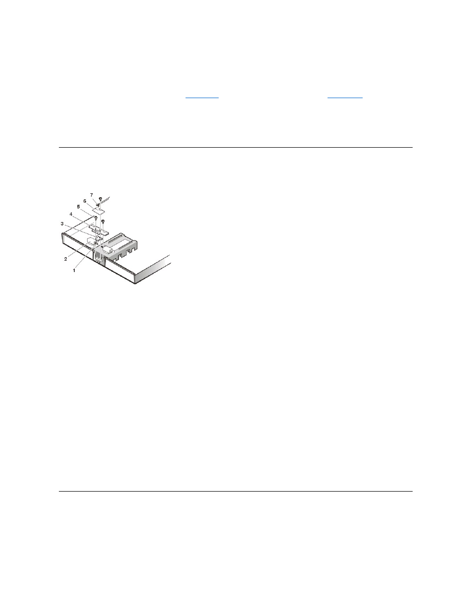
Figure 38. Latch Assembly Components
To remove the latch assembly (see Figure 38), perform the following steps:
1. Disconnect the LED cable from connector JP2 on the LED board.
2. Remove the 4-mm screw securing the LED board to the plastic base.
3. Remove the LED board.
4. Remove the two 4-mm screws holding the latch cover for the MegaBay and media bay.
5. Remove the latch cover.
6. Remove the center lock over the two latches with springs.
7. Remove each spring and latch.
Be careful not to lose the small springs.
Display Assembly and Display Assembly Component Removal
Figure 39. Display Assembly Removal
1 10-mm screw
2 Audio thermal shield
3 Audio card
1 Springs (2)
2 Latches (2)
3 Center lock
4 Latch cover
5 4-mm screws (3)
6 LED board
7 LED cable