Dell PowerVault DR6000 User Manual
Page 48
•
System Hardware Health (table)—shows the current status for all of the major hardware subcomponents in the
appliance:
– Power Supplies—status, name, and location
– Fans—status, name, speed, and identifier
– Temperature—status, name, and temperature
– Storage—storage controller, storage virtual disks, storage physical disks, storage controller battery, and
storage cache
NOTE: The storage controller battery state displays either as
Ready
or
Charging
(the latter indicates this
state after a system reboot until the storage controller battery is fully charged).
– Voltage—status, name, voltage, and probe name
– NIC (network interface card)—status, name, type, and speed
– CPU (central processing unit)—status and name
– DIMM (dual in-line memory module)—status, name, and connector name
– NVRAM (non-volatile random access memory)—NVRAM (status, name, errors, temperature, SSD state, SSD
health, SSD firmware version, serial number, and firmware version); NVRAM super capacitor (status, name,
state, voltage, and maximum design voltage)
NOTE: To display the current status, name, and state of chassis components, hover your mouse over the
component.
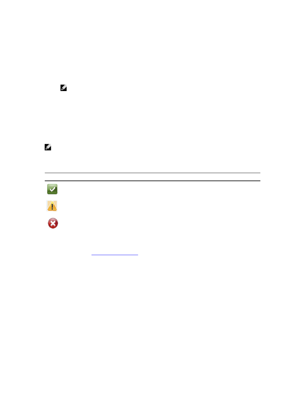
All system hardware components are listed in the System Hardware Health pane by component name, status, and other
attributes. The following table identifies the component status by one of three color-coded icons that reflect its state.
Icon
Description
This color code icon indicates that the component status is operating at an optimal state.
This color code icon indicates that the component status is a operating under a warning state (a
non-critical error has been detected).
This color code icon indicates that the component status is operating under an error or
actionable state (a critical error has been detected).
To expand any component category to display more status details for each related subcomponent, click + ("plus sign"
icon) in the System Hardware Health pane. To contract any expanded component category, click — ("minus sign" icon).
For more information, see
DR Series System Enclosures
In the Enclosure tab on the Health page, the following images and System Hardware Health table display the status of
the expansion shelf enclosure components (for specific locations, see Figure 4).
48