Installing a drive in the 5.25-inch drive bay – Dell OptiPlex E1 User Manual
Page 70
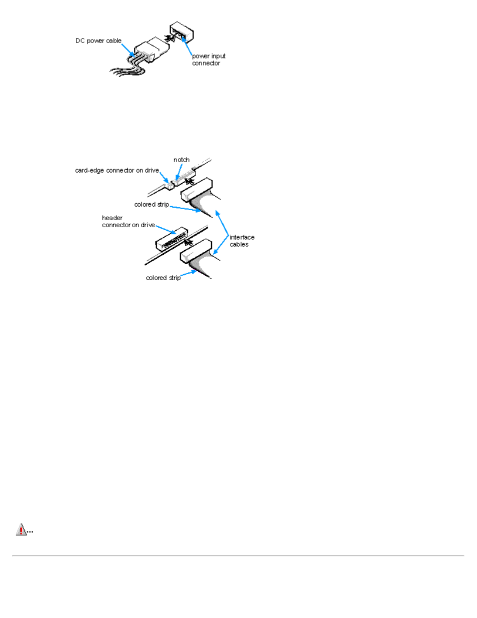
Figure 7-4. DC Power Cable Connector
The drive's interface connector is a card-edge connector or a header connector, as shown in Figure 7-5.
Figure 7-5. Drive Interface Connectors
When attaching the interface cable to a drive, be sure to match the colored strip on the cable to pin 1 of the drive's interface
connector. For the location of pin 1 on the drive's interface connector, see the documentation that came with the drive.
When disconnecting an interface cable from the system board, be sure to press in on the locking tabs on the cable connector
before disconnecting the cable. When attaching an interface cable to the system board, be sure that the locking tabs snap into
place, ensuring that the cable is firmly attached to the connector on the system board.
Most interface connectors are keyed for correct insertion; that is, a notch or a missing pin on one connector matches a tab or a
filled-in hole on the other connector. Keying ensures that the pin-1 wire in the cable (indicated by the colored strip along one edge
of the cable) goes to the pin-1 end of the connector.
The pin-1 end of a card-edge connector is usually identified by a notch cut about a quarter of an inch from the end of the
connector, as shown in Figure 7-5. A header connector is usually keyed by the omission of one of its pins, while the corresponding
hole is filled in on the cable connector.
The pin-1 end of a connector on a board or a card is usually indicated by a silk-screened "1" printed directly on the board or card.
CAUTION:
When connecting an interface cable, do not reverse the interface cable (do not place the colored strip
away from pin 1 on the connector). Reversing the cable prevents the drive from operating and could damage the
controller, the drive, or both.
Installing a Drive in the 5.25-Inch Drive Bay