Dell OptiPlex E1 User Manual
Page 53
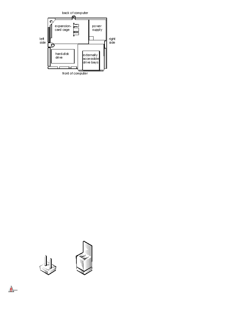
Figure 5-4. Computer Orientation View
Figure 5-5 shows your computer with its cover removed. Refer to this illustration to locate interior features and components
discussed in this guide.
When you look inside your computer, note the DC power cables coming from the power supply. These cables supply power to the
system board; to internal diskette drives, hard-disk drives, and tape drives; and to certain expansion cards that connect to external
peripherals.
The flat ribbon cable in Figure 5-5 is typical of the interface cables for internal drives. An interface cable connects a drive to a
connector on the system board or on an expansion card.
The system board—the large printed circuit board at the bottom of the chassis—holds the computer's control circuitry and other
electronic components. Some hardware options are installed directly onto the system board.
During an installation procedure, you may be required to change a jumper setting on the system board and/or a jumper or switch
setting on an expansion card or on a drive. Jumpers and switches provide a convenient and reversible way of reconfiguring the
circuitry on a printed circuit board. For information on jumpers and switches, see the following two subsections.
Jumpers
Jumpers are small blocks on a circuit board with two or more pins emerging from them. Plastic plugs containing a wire fit down
over the pins. The wire connects the pins and creates a circuit.
To change a jumper setting, pull the plug off its pin(s) and carefully fit it down onto the pin(s) indicated.
CAUTION:
Make sure your system is turned off before you change a jumper setting. Otherwise, damage to your
system or unpredictable results may occur.