Edge Lighting PSB-400W-24VDC-RGB, 400 Watt 24 Volt DC Power Supply User Manual
Page 4
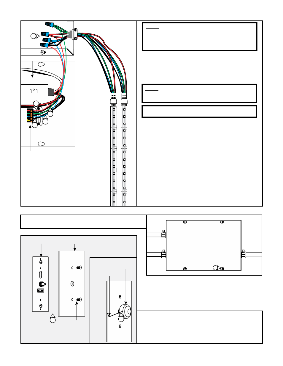
19: Use the "Low Voltage Wire Size Chart" on page 1 to
determine proper wire size connecting to the DVR-RGB-200
terminals.
20: Run the proper size green, red, blue, and black wires from
the RGB LED soft strip to the power supply case.
NOTE: The DVR-RGB-200 terminals adapt maximum 18
AWG size. To avoid voltage drop, use 6" of 18 AWG size in
RGB terminals connected inline to proper size gauge wire
attached to the RGB LED wires with wire nuts. See the
"Low Voltage Wire Size Chart" on page 1.
NOTE: This power supply is supposed to be used for
multiple runs of RGB soft strip. Do not exceed the
maximum wattage of the power supply.
NOTE: Use only 24 volt RGB LED soft strip with this
power supply.
21: Connect the soft strip black wire into power supply "+V"
terminal. Connect the other end to RGB soft strip black
wire(s).
22: Connect the soft strip red wire into DVR "Group 1-" red
terminal. Connect the other end to RGB soft strip red
wire(s).
23: Connect the soft strip green wire into DVR "Group 2-" green
terminal. Connect the other end to RGB soft strip green
wire(s).
24: Connect the soft strip blue wire into DVR "Group 3-" blue
terminal. Connect the other end to RGB soft strip red
wire(s).
25: Replace the DVR-RGB-200 cover.
19
POWER SUPPLY
DVR-RGB-200
20
23
22
E
26: Replace the power supply cover and secure it by tightening
the four Phillips screws.
F
0-10V
Dimming
LED +
LED -
L N G
0-10V
Dimming
LED +
LED -
L N G
26
4
21
27: Align the face plate to the controller and secure using the
two flat head screws.
28: Attach the push button onto the controller center rod and
secure by tightening the M3 set screw with the 1.5mm Allen
wrench provided.
G
O N
1
2
3
4
5
6
7
CONTROLLER
FACE PLATE
FLAT HEAD
SCREW
PUSH
BUTTON
1.5MM ALLEN
WRENCH
27
28