115v – Edge Lighting PSB-400W-24VDC-RGB, 400 Watt 24 Volt DC Power Supply User Manual
Page 3
+V
-V
L
N
3
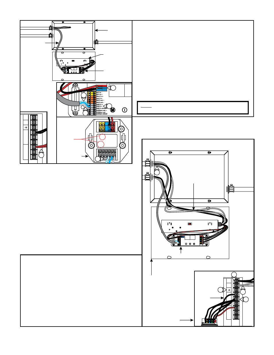
10: Install a red wire from the power supply "+V" terminal to
DVR-RGB-200 "VDC+" red terminal and a black wire from
power supply "-V" terminal to DVR-RGB-200 "VDC-" blue
terminal.
11: Connect one end of a data wire (blue with white stripes
wire) to controller "LEDSYNC OUT–" terminal. Connect the
other end into the DVR-RGB-200 "DMX in –" terminal.
12: Connect one end of a data wire (white with blue stripes
wire) to controller "DMX +" terminal. Connect the other
end into the DVR-RGB-200 "LEDSYNC OUT+" terminal.
13: Connect one end of a data wire (bare shield wire) to
controller "LEDSYNC SHIELD" terminal. Connect the other
end into the DVR-RGB-200 "DMX in shield" terminal.
M
CASE
COVER
POWER SUPPLY
DVR-RBG-200
DMX CABLE
C
13
11
12
10
14: Run the line voltage power wires into the power supply.
15: Connect the black power wire and the black controller
wire to the "L" terminal of the power supply.
16: Connect the white power wire and the white controller
wire to the "N" terminal of the power supply.
17: Make sure the power supply ground terminal is grounded
in accordance with local electrical codes.
18: Connect three black wires to the DVR-RGB-200 "GROUP 1
GND", GROUP 2 GND", and "GROUP 3 GND" black terminal
to the power supply "-V" terminal.
D
M
COVER
DVR-RGB-200
CONTROLLER LINE VOLTAGE
POWER SUPPLY WIRES
POWER
SUPPLY
14
115V
115V
+V
-V
L
N
15
16
17
18
10
EXT in-
EXT in+
VDC-
VDC+
DMX in +
DMX in -
DMX in
shield
LEDSync
out +
LEDSync
out-
LEDSync
out shield
DVR-RGB-200
12
CONTROLLER
NOTE: "DMX in+", "DMX in-", "EXT in+" & "EXT in-",
controller terminals are not used on controller.
DO NOT
USE