96w, 24vdc low voltage wire size chart – Edge Lighting Cirrus Channel, Wall Grazer User Manual
Page 5
5
R
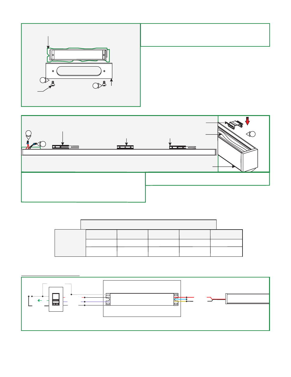
MOUNTING
CLIP (C-MCL)
WIRE
MANAGEMENT
CLIP
CORD
CHANNEL
16
14
15
14: Connect the red power supply (24VDC+) wire to red strip
wire with a wire nut inside the Junction box.
15: Connect the black power supply (24VDC-) wire to black
strip wire with a wire nut inside the Junction box.
VOLTAGE
DROP
UP TO 33FT
3%
34FT-52FT
WIRE SIZE
VOLTAGE AT END
OF THE WIRE
14 AWG
23.28 VDC
53FT-86FT 87FT-130FT
12 AWG
23.29 VDC
10 AWG
8 AWG
23.28 VDC
23.28 VDC
WIRE LENGTH
IN FT
96W, 24VDC LOW VOLTAGE WIRE SIZE CHART
PSB-96W-010-24VDC
WHITE (NEUTRAL)
GENERAL WIRING DIAGRAM
input 120VAC
WH (N)
BK (L)
input 0-10V
PUR
GRY
RED (24VDC+)
BLUE (RETURN-)
YELLOW (DIM RETURN-)
INPUT
120VAC
LIGHTOLIER:
ZP600FAM120
CONTROLLER
24VDC
RED 24VDC+
BLACK 24VDC-
PURPLE 1-10V
GRAY 1-10V
RED 120VAC (HOT)
BLACK (HOT)
GND
CIRRUS CHANNEL
DIMMING
LOCKING
BRACKET
16: Snap the wire management clip to hold the cable in place if
necessary.
13: Optional: Use the Goof Plate if the junction box
opening has a lot of imperfection/jagged edges. Install the
provided goof plate (paint to match prior) with the two
screws.
Q
JUNCTION BOX
OPENING EDGE
GOOF PLATE
(ONLY USE IF JAGGED
PLASTER EDGE, PAINT
TO MATCH)
SCREW
13
PLASTER THE EDGE OF
THE JUNCTION BOX
13
LOCKING CLIP