Edge Lighting Cirrus Channel, Wall Grazer User Manual
Page 4
4
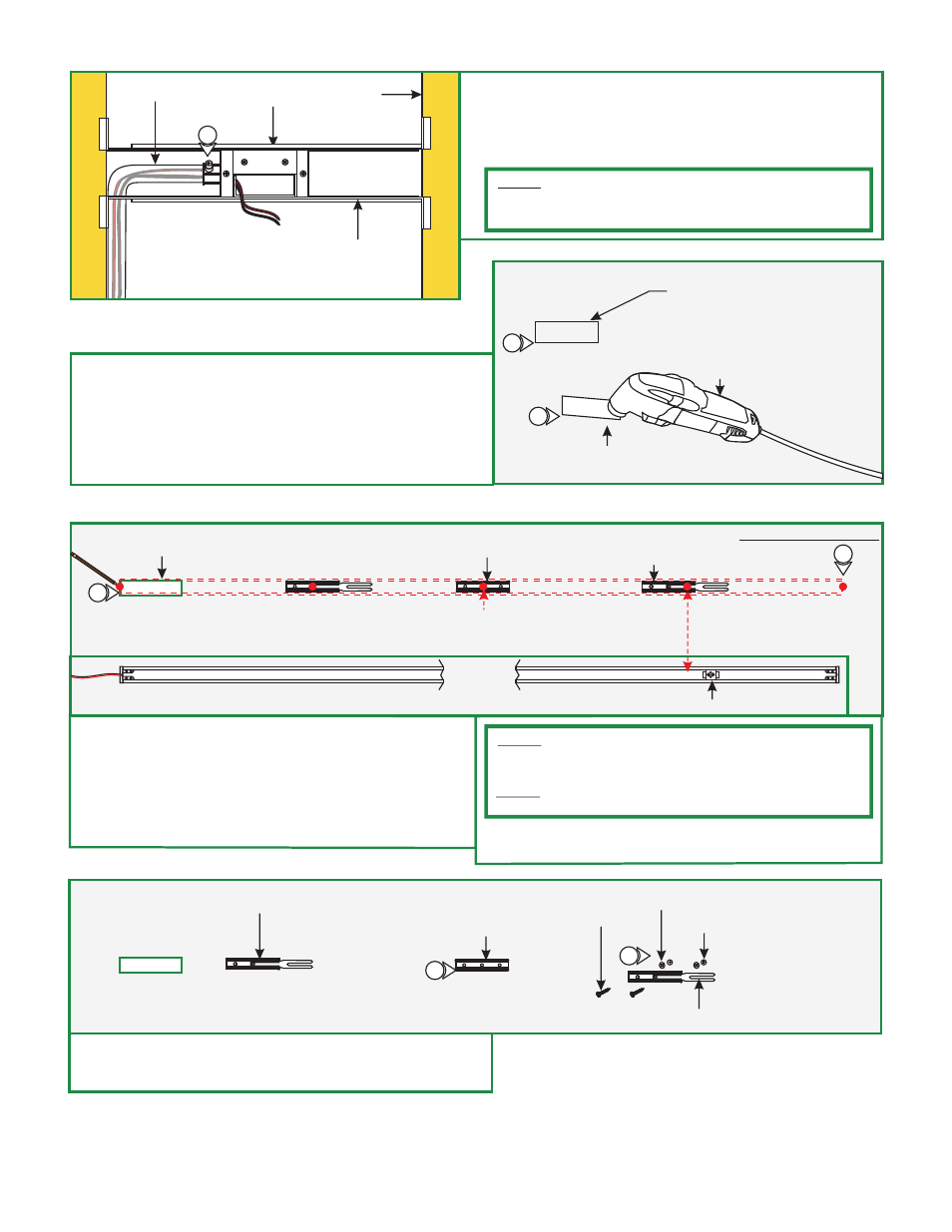
5: Remove a knockout to install the power line conduit.
6: Install the conduit and run the low voltage 24V DC power
wires coming from the remote power supply to the
Junction box.
NOTE:
Remote power supply must be installed within 40ft of
Junction box. The low voltage 24V DC wires must be present in
Junction box. See wiring diagram on page 5 for more information.
M
STUD
ADJUSTABLE
MOUNTING BAR
CONDUIT
JUNCTION BOX
5
N
7
DRYWALL
RECTANGLE
OPENING
7:
opening will be located depending on selected position.
8: Cut out the marked rectangle opening, using a "Dremel
Multi-Max" with the "wood & drywall" cutting bit.
9: Install & finish drywall.
Mark a rectangle shape on drywall where the junction box
DREMEL
MULTI-MAX
WOOD & DRYWALL
CUTTING BIT
8
JUNCTION BOX
OPENING
NOTE:
If the receiving bracket interferes with the Junction box,
then relocate the bracket by loosening the set screws and make
the necessary adjustments.
NOTE:
The channel must pass through the center of the
Junction box.
10: Start off the installation using the channel with the power
wire. Lay the channel to the desired location & make all
necessary markings which will consist of the channel ends,
locking clips and mounting clips. Mounting clips must be
installed every 20" from each locking clip, locking
mounting clips are not necessary for channels under
2ft.
11: After all markings and required measurements are done,
take the channels apart from each other.
BOTTOM OF CHANNEL
RECEIVING BRACKET
O
POWER FEED END
OF CHANNEL
CHANNEL
END
MOUNTING
CLIP (C-MCL)
MARKING LOCATION
LOCKING CLIP
(OPPOSITE SIDE OF POWER WIRE)
10
EVERY 20 INCHES
10
P
MOUNTING
CLIP (C-MCL)
12: Line up the locking clips & mounting clips to anchor holes
and secure them by tightening the two #6 screws through
the clip holes followed by the washers into the anchors.
12
12
LOCKING CLIP
WASHER
(OPTIONAL)
ANCHOR
LOCKING CLIP
#6 SCREW