Amico Falcon Combo Arm User Manual
Page 10
10 Amico Accessories Inc.
Mounting To The VRS(Vertical Rail System) / Ohmeda Rail
FIT Station
WARNING
All V-adapters must be sitting in the VRS securely. If not, serious injury could result.
WARNING
To prevent the V-adapter from falling down the VRS, ensure that the screws are fastened to the
tightest possible position. After the installation, rotate the AHM arm side to side to verify that no movement
is present between the adapters and the VRS.
WARNING
Ensure rail is stable and properly installed before mounting FIT Station.
WARNING
The Mounting Adapter for Ohmeda rails differ from the Mounting Adapter for VRS, the
Adapters are not cross-compatible.
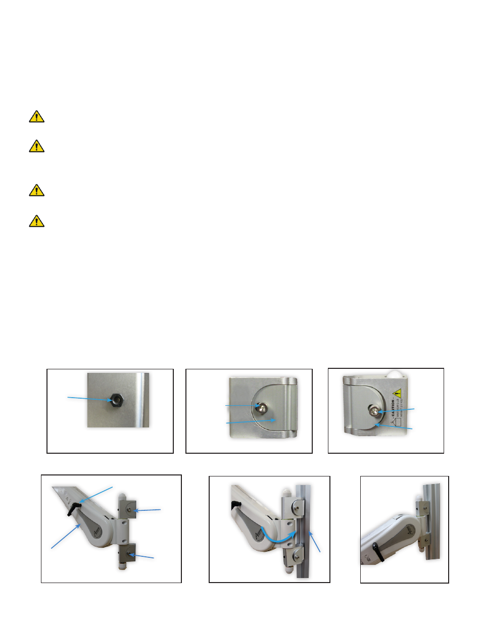
NOTE:
When the screw is turned clockwise, it causes the side of the V-adapter to slide inward,
locking the V-adapter (Figure 2). When the screw is turned counter-clockwise, it causes the side of the
V-adapter to slide outward, unlocking the V-adapter. (Figure 3)
Ensure the V-Adapter is in the UNLOCKED position, and ensure the AHM is LOCKED in the highest vertical position.
NOTE:
See Page 25 for instructions on locking and unlocking the AHM
1. Angle the AHM from the left of the channel and guide the adapters into the groove of the channel. (Figure 4
and 5)
2. Tighten screw with a 3/16’’ HEX key when V-adapter is at the desired height. When tightened, the screw
will protrude from the other side. Fasten the nut to the screw to secure the V-adapter. If the nut cannot be
installed, the adapter is not properly engaged. Check that all nuts and screws are tightened to ensure the
V-Adapter is locked. (Figure 6)
(Figure 1)
Opposite side of the
V-adapter
Nut
(Figure 2)
Locked
Slide
inwards
Screw
(Figure 3)
Slide
outwards
Unlocked
Screw
(Figure 4)
AHM
V-Adapter
Screws
(Figure 5)
(Figure 6)
Mounted on the VRS
Height Locking Lever
VRS
SECTION 2: Installation on Rail Systems