Loading dry fertilizer (twin row), Suitable materials, System inspection – Great Plains YP825AR Operator Manual User Manual
Page 46: Hopper lid operation
42
YP825AR
Great Plains Manufacturing, Inc.
401-923M
2014-06-17
Loading Dry Fertilizer (Twin Row)
Loading liquid fertilizer is found on page 39.
If fertilizer will not be applied, uncouple the fertilizer
meter shaft at the left end of the left hopper. Pin the
coupler clear of the shaft joint.
Loading fertilizer prior to transport is not recommended.
Although the meters are not turning during transport, it is
possible for some material to spill through the meters,
particularly on rough roads.
Suitable Materials
Use only dry granular fertilizer. Granules must flow freely,
and must have a maximum diameter smaller than 7 mm
(to avoid bridging clogs in the applicator tube outlets).
Agricultural Chemical Hazard:
Wear protective equipment suitable for the material to be used,
and the material previously dispensed from the hoppers. Avoid
contact with skin or eyes. Avoid breathing dust.
System Inspection
Verify that both rear cradle pins are installed on all
hoppers. See Figure 114 on page 99.
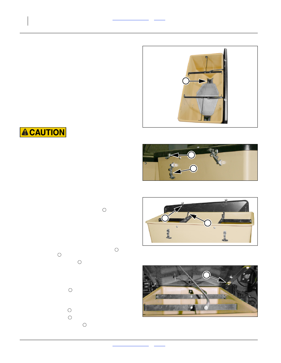
Refer to Figure 42
Remove the lid on each hopper and inspect for:
• residual fertilizer incompatible with next use
• contaminants
• debris that might clog the meter inlets
• trapped animals lost tools, etc.
If it is necessary to clean a hopper, see “Dry Fertilizer
Clean-Out” on page 99.
Hopper Lid Operation
Refer to Figure 43 and Figure 45
To unlock the hopper lid, lift the rubber latches
out of
the metal keepers
.
Note: The keeper hardware
tends to snag under the
hopper lip. Pull the lid edge forward and lift.
Refer to Figure 44
To open the lid, lift the front edge up and slide the lid
back into a vertical position behind the hopper. The lid is
held by retaining straps
.
Refer to Figure 43, 44 and 45
When closing the lid make sure that:
• the rear catch plates
are under the hopper rear lip,
• the keeper hardware
is under the front lip, and
• the ball of each rubber latch
is seated in the keeper.
(If only the handle “T” is seated, the lid is not secure.)
Figure 42
Empty 2- Outlet Hopper
31866
1
Figure 43
Hopper Latch Open and Closed
31866
2
3
Figure 44
Hopper Lid Open
31865
4
5
1
2
3
Figure 45
Hopper Lid Rear Catch Plate
31864
6
4
5
5
4
2