Marker extension table – Great Plains YP825AR Operator Manual User Manual
Page 156
152
YP825AR
Great Plains Manufacturing, Inc.
401-923M
2014-06-17
3.
Tilt up and unfold one marker.
Find the suggested initial marker Extension
in the
table on this page.
Note: When using altered twin-row spacings, marker
extensions are different for left and right.
Refer to Figure 132 and Figure 133
4.
Measure out the Extension
distance from each
outside end row unit (whether in use or not). Do not
measure to center of row pair.
5.
Mark the ground at this point.
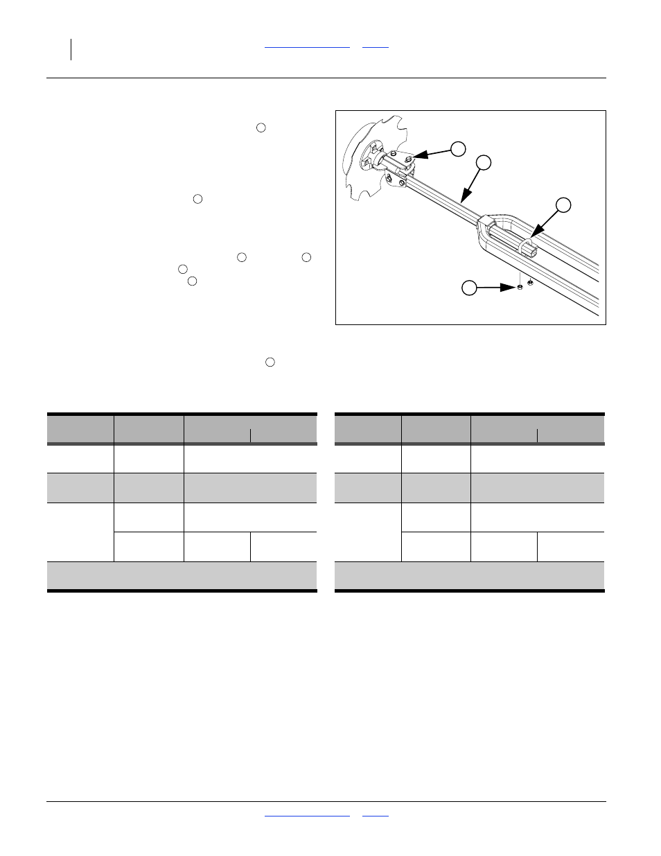
6.
To adjust marker width, loosen nuts
on U-bolts
.
Move marker disk tube
in or out to get the proper
adjustment. Tighten nuts
.
7.
Repeat steps 3 through 6 for the other side.
8.
With the planter still lowered, drive forward a few feet
for each side.
9.
Check mark locations. Adjust to obtain table value.
10. if it is necessary to adjust the disk angles
for a
more suitable field mark, be sure to re-check the
extension.
Marker Extension Table
Figure 133
Marker Extension Adjustment
34726
1
2
3
4
e
e
1
2
3
1
4
Planter
Spacing
Marker Extension
Planter
Spacing
Marker Extension
Model
Used
Left
Right
Model
Used
Left
Right
YP825AR
Standard:
99.0 in
YP825AR
Standard:
315.0 cm
-0822 22 in. Single
(251.5 cm)
-0870 70 cm Single
(124.0 in.)
YP825AR
Standard:
135.0 in
YP825AR
Standard:
337.5 cm
-0830 30 in. Single
(342.9 cm)
-0875 75 cm Single
(132.9 in.)
Standard:
130.8 in
Standard:
326.9 cm
YP825AR
30 in. Twin
(332.3 cm)
YP825AR
75 cm Twin
(128.7 in.)
-16TR30
as:
122.4 in
139.2 in
-16TR75
as:
305.6 cm
348.1 cm
30 in. Single
(311.0 cm)
(353.5 cm)
75 cm Single
(120.3 in.)
(137.1 in.)
as Single:
as Single:
Right (front) rows in use; left (rear) rows
locked up. No centerline compensation.
Right (front) rows in use; left (rear) rows
locked up. No centerline compensation.