Appendix c - initial setup, Post-delivery checklist, Initial marker setup (option) – Great Plains YP825AR Operator Manual User Manual
Page 154: Marker speed adjustment
401-923M
2014-06-17
150
YP825AR
Great Plains Manufacturing, Inc.
Appendix C - Initial Setup
This Appendix covers setup tasks performed only once,
or at infrequent intervals. Routine setup tasks are
covered in “Preparation and Setup” on page 13.
Perform Appendix B tasks first. Some of these items may
already have been done by your Great Plains dealer:
a.
Frame-mounted row options
(see manual supplied with accessory)
b.
Marker setup (Option, page 150)
c.
High rate dribblers (Option, page 153)
d.
e.
Fertilizer drop lines (Option, page 155)
Initial Marker Setup (Option)
Marker Speed Adjustment
Overhead Sharp Object and Crushing Hazards:
Never allow anyone near the planter when folding or
unfolding the markers. You may be injured if hit by a folding or
unfolding marker. Markers may fall quickly and unexpectedly
if the hydraulics fail. Marker discs may be sharp.
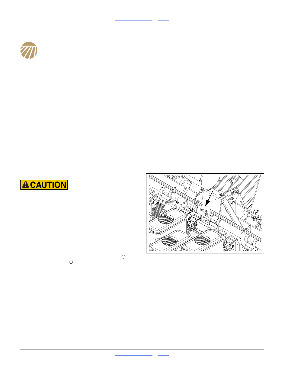
Refer to Figure 130 and Figure 131
Adjust folding speed for dual markers with hex
adjustment screws on the sequence valve body. The
valve sequence body is rear center on the lift structure,
below the fan. Loosen jam nuts before making
adjustments.
There is one adjustment screw for raising speed
and
one for lowering speed
. You can identify adjustment
screws by markings stamped in valve body.
Post-Delivery Checklist
1.
Read and understand “Important Safety
Information” on page 1.
2.
Check that all working parts are moving freely, bolts
are tight, and cotter pins are spread.
3.
Check that all grease fittings are in place and
lubricated. See “Lubrication and Scheduled
Maintenance” on page 108.
4.
Check that all safety decals and reflectors are
correctly located and legible. Replace if damaged.
See “Safety Decals” on page 6.
5.
Inflate tires to pressure recommended and tighten
wheel bolts as specified. See “Tire Inflation Chart”
on page 134.
Figure 130
Marker Sequence Valve Location
34805
1
2