About the frame control switch, Color function – Great Plains YP825AR Operator Manual User Manual
Page 29
Great Plains Manufacturing, Inc.
Operating Instructions
25
2014-06-17
401-923M
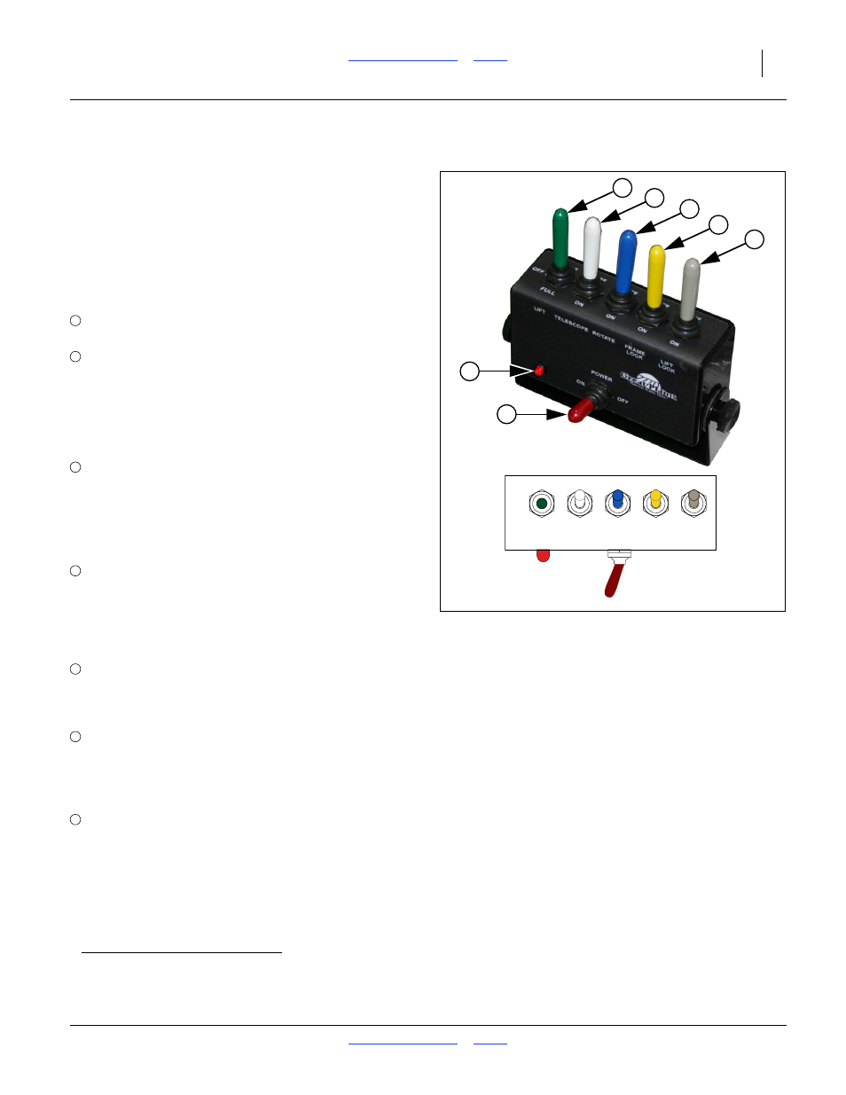
About the Frame Control Switch
Two planter hydraulic circuits (lift/lift-lock/marker and
rotate/frame-lock/telescope) have multiple cylinders
sharing the circuit.
Which cylinder set has the circuit is controlled by a
switch box in the tractor cab, a solenoid valve block on
the planter, and limit switches on the planter.
Refer to Figure 14
Set circuit tractor remotes to Neutral before activating
switches. Do not operate solenoid valves
b
under
pressure.
Instruction steps have only one switch out of “OFF”
position at a time.
The planter limit switches prevent most, but not all
incorrect operations. Follow instruction steps carefully.
Do not rely on the protection of limit switches
for routine
operations.
The solenoid valves are spring-loaded to OFF. If power is
off, or harnesses are not connected at the hitch, normal
hydraulic operations are not possible.
a. If no markers are installed, or the marker shut-off valve (page 26) is closed, OFF locks lift cylinder motion. If markers are installed, with
manual shut-off valve on, lift/marker motion is still possible with the LIFT switch (or POWER) OFF. See page 26 for details.
Color
Function
Red
POWER: ON makes +12 Vdc available to the
selector and limit switches.
Red
LED: Illuminates when tractor +12 Vdc is
available to the switch box, and the POWER
switch is ON.
Note: An illuminated LED does not necessarily
indicate that the harnesses are
connected at the hitch.
Green LIFT: Circuit: lift/lift-lock/markers
OFF: Lift/Marker
a
circuit cut off from tractor.
HALF: Lift cylinders enabled, but travel is
inhibited at and above field lift by a limit switch.
FULL: Lift cylinder travel is unrestricted.
White TELESCOPE:
Circuit: telescope/rotate/frame-lock
ON: Enables telescoping tongue cylinder
operations
OFF: Disables telescoping operations
Figure 14
Frame Control Switch Box
34700
34705
1
6
5
4
7
3
2
HALF
OFF
OFF
OFF
OFF
OFF
FULL
ON
ON
ON
ON
LIFT
TELESCOPE ROTATE
FRAME
LOCK
LIFT
LOCK
POWER
ON
OFF
1
2
3
4
Blue
ROTATE: Circuit: telescope/rotate/frame-lock
ON: Enables opener frame rotate operations
OFF: Disables opener frame rotate operations
Yellow FRAME LOCK:
Circuit: telescope/rotate/frame-lock
ON: Enables cylinder for tongue/pivot lock
OFF: Disables cylinders for tongue/pivot lock
Gray
LIFT LOCK: Circuit: lift/lift-lock/markers
ON: Enables cylinders for lift lock pins
OFF: Disables cylinders for lift lock pins
5
6
7
b. Exception: the LIFT solenoid valve is designed to cut off active flow to the lift/lift-lock/marker circuit during field (HALF) lift.