Side gauge wheel adjustments – Great Plains YP1625A Operator Manual User Manual
Page 70
66
YP1125A & YP1625A
Great Plains Manufacturing, Inc.
401-625M
2013-08-13
Side Gauge Wheel Adjustments
Refer to Figure 82
The side gauge wheels have two, interrelated
adjustments:
• angle of side gauge wheel, and
• distance between side gauge wheels and discs.
Refer to Figure 83
Adjust side-gauge-wheel angle so wheels contact
row-unit discs at the bottom of wheel at 2in planting
depth and gaps open
3
⁄
8
to
5
⁄
8
inches (9.5 to 16 mm) at
top. Check with row-units in soil so wheels are held up.
At the same time, keep side gauge wheels close to
opener discs so openers do not plug with soil or trash.
However, wheels should be out far enough so discs and
wheels turn freely.
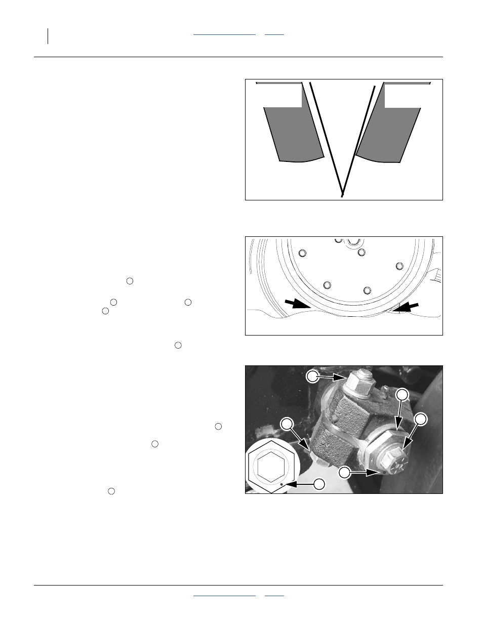
Refer to Figure 84
To adjust side gauge wheels:
1.
Raise planter slightly removing weight from side
gauge wheels.
2.
Loosen hex-head bolt
. Move wheel and arm out
on o-ring bushing.
3.
Loosen pivot bolt
. Turn hex adjuster
so
indicator notch
is at 5 o’clock to 7 o’clock.
Note: Use this as the starting point for adjustment.
4.
Move wheel arm in so side gauge wheel contacts
row unit disc. Tighten hex-head bolt
to clamp arm
around bushing and shank.
5.
Check wheel-to-disc contact at 2 inches (5 cm)
planting depth. Lift wheel 2 inches (5 cm) and
release. When let go, wheel should fall freely.
• If wheel does not contact disc at bottom to area where
blade leaves contact with soil, move hex adjuster until
wheel is angled for proper contact with disc.
• If wheel does not fall freely, loosen hex-head bolt
and slide wheel arm out just until wheel and arm move
freely. Retighten hex-head bolt
per grade:
1
⁄
2
inch Grade 5 bolt, 76 foot-pounds (105 N-m).
1
⁄
2
inch Grade 8 bolt, 110 foot-pounds (150 N-m).
6.
Keep turning hex adjuster and moving wheel arm
until the wheel is adjusted properly. When satisfied,
tighten pivot bolt
to 110 foot-pounds.
Note: Use “End of “Appendix A - Reference
Information”.” on page 140 for reference.
Incorrect
Correct
Side Gauge
Wheel
Opener
Discs
Side Gauge
Wheel
Figure 82
Disc/Gauge Wheel Alignment
Figure 83
Opener-Gauge Wheel Contact
22531
Contact Within this Area
1
2
3
4
1
Figure 84
Disk/Gauge Wheel Adjustment
22524
22525
Starting Point
1
1
4
4
3
2
1
1
2