Install marker extension tube, Check disk orientation, Insert and secure tube – Great Plains YP1625A Operator Manual User Manual
Page 148
144
YP1125A & YP1625A
Great Plains Manufacturing, Inc.
401-625M
2013-08-13
Install Marker Extension Tube
Check Disk Orientation
Refer to Figure 150 (C: to Center; W: to Wing)
18. Select one:
113-794D MARKER EXTENSION TUBE
These tube assemblies
are identical for LH and
RH use. The disk and spindle
are pre-assembled.
Prior to installing the marker extension tube, inspect
the disk assembly. The bolts securing the spindle
weldment to the tube are to be vertical after
installation, and the spindle
is to be to the front.
This is merely the factory default orientation. The
operator may change it as needed.
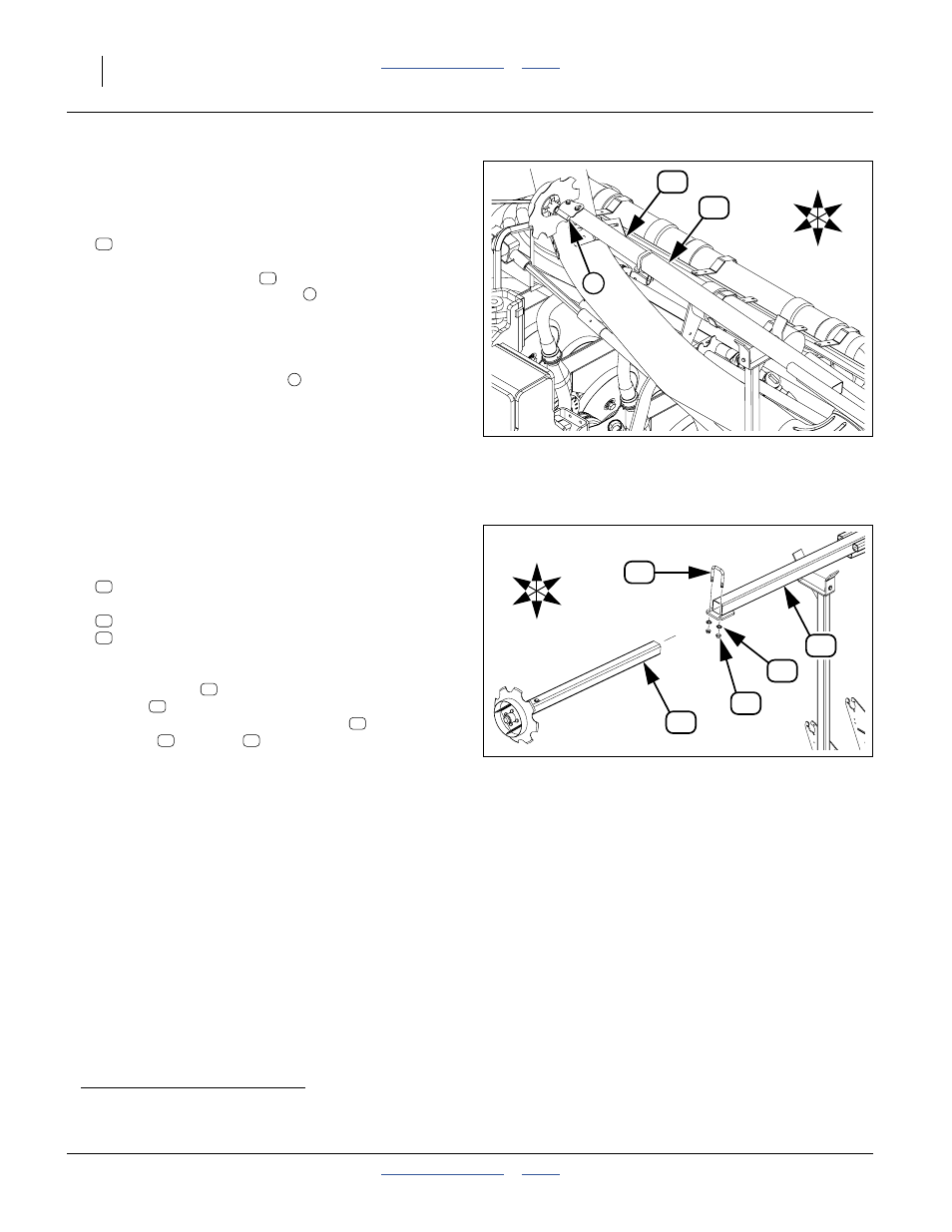
Insert and Secure Tube
For each wing:
Refer to Figure 151 (C: to Center; W: to Wing)
19. Select one:
806-110C U-BOLT 5/8-11 X 3 1/32 X 4 1/2
and two sets:
804-022C WASHER LOCK SPRING 5/8 PLT
803-021C NUT HEX 5/8-11 PLT
Minding the spindle orientation, insert the marker
extension tube
into the marker arm second
section
to a depth of about
a
18 inches (45 cm).
Secure the extension with the U-bolt
, lock
washers
and nuts
.
Figure 150
LH Marker Spindle Orientation
34386
11
5
U
D
F
B
W
C
14
14
14
a. Exact extension value depends on row spacing, row utilization and desired disk angle. Setting this requires full monitor and hydraulic
connections, then unfolding the planter and markers in field conditions. See “Marker Setup” on page 150.
Figure 151
LH Marker Extension Tube
24408
U
D
C
W
F
B
41
14
38
32
11
41
38
32
14
11
41
38
32