Marker operation – Great Plains YP1625A Operator Manual User Manual
Page 48
44
YP1125A & YP1625A
Great Plains Manufacturing, Inc.
401-625M
2013-08-13
Marker Operation
Electrocution Hazard:
Check for overhead lines before operating markers. If a
marker contacts an electrical line, all metal parts of the
planter and tractor can have lethal voltages present. There
may be no indication of this condition until a person completes
the circuit to ground. At higher voltages, electrocution can
occur without direct contact.
Before operating markers, make sure they are properly
bled as described in “Bleeding Hydraulics” on page 97.
For markers to operate, the marker hydraulic circuit must
be enabled:
Refer to Figure 52
1.
On the CFM switch panel, set the “Marker/Fold”
switch
to Marker. Leave this switch in “Marker”
position for all field operations. It also acts to lock the
folding system when in “Marker”.
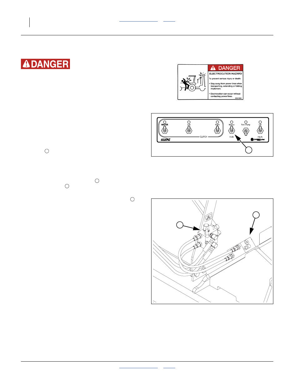
Refer to Figure 53
2.
If the planter is equipped with an auxiliary hydraulic
system, set the selector valve
(found near the
sequence valve
at the marker base on the left
wing) to “Marker”.
Dual markers are equipped with a sequence valve
to
control lift sequence. Starting with both markers up, the
sequence is:
1.
Activate tractor hydraulic lever; right marker lowers
while left marker stays up.
2.
Reverse hydraulic lever; right marker raises while left
marker stays up.
3.
Activate hydraulic lever; left marker lowers while right
marker stays up.
4.
Reverse hydraulic lever; left marker raises while right
marker stays up.
5.
Pattern repeats.
Folding speed of dual markers is adjusted with
adjustment screws on sequence valve body. Because
excessive folding speed may damage markers, adjust
markers to a safe folding speed according to “Marker
Adjustments” on page 56.
Note: To get both markers in the lowered position at the
same time, activate hydraulic lever to lower one
marker. After marker is lowered, move lever to
opposite position then quickly reverse lever and
hold until other marker is lowered.
Figure 52
CFM: Markers Enabled
28491
1
1
2
3
Figure 53
Aux Valve Set to Markers
28493
2
3
3