Appendix c - initial setup, Hydraulic charge and bleed, Console installation – Great Plains YP1625A Operator Manual User Manual
Page 150: Monitor setup, Yp1225a row spacing setup data, Yp1625a row spacing setup data
401-625M
2013-08-13
146
YP1125A & YP1625A
Great Plains Manufacturing, Inc.
Appendix C - Initial Setup
Hydraulic Charge and Bleed
Connect the planter to a suitable hydraulic source and
check the condition of the hydraulic systems:
“Unfolding The Planter” on page 20,
“Raising/Lowering Planter” on page 24,
“Folding the Planter” on page 25,
“Fan Circuit Operation” on page 42,
“Marker Operation” on page 44, and if hydraulic drive is
installed, run a “FILL DISK” sequence to check motor.
See “Bleeding Hydraulics” on page 97 if any circuits do
not operate smoothly.
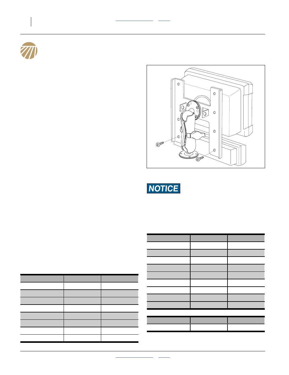
Console Installation
The planter’s standard seed monitor system includes a
virtual terminal and switch panel that must be mounted in
the tractor cab. As supplied by DICKEY-john
®
, the kit
includes a flat bracket for the modules, and ball swivel for
mounting the bracket in the tractor.
The ball swivel includes four 10-32 screws. You or your
dealer must provide the mounting holes for the screws.
Your dealer may have alternate suction cup or clamping
brackets available if you prefer to avoid drilling holes.
Refer to the DICKEY-john
®
manual for harness
connections. Route wiring harnesses with enough slack
to allow for tractor movement, especially on articulating
tractors.
Monitor Setup
Refer to the DICKEY-john
®
IntelliAg
®
Operator manual
for general system information. Data specific to your
planter model is provided in a separate Quick Start
Guide. Configure the system with this information prior to
first use. The Quick Start guides, however, are not
specific to individual model row spacings. Use the
following data:
YP1225A Row Spacing Setup Data
YP1625A Row Spacing Setup Data
Mount the modules so that they are easy to monitor during
planting, but do not interfere with safe operation of the tractor
in the field or on public roads.
Figure 154
Terminal and Switch Panel
26303
Model
Active Rows
Channel Width
YP1225A-1230
12
360 in
YP1225A-16TR36
16
288 in
as -0836
8
288 in
YP1225A-1820
18
360 in
YP1225A-2315
23
345 in
as -1230
12
360 in
YP1225A-24TR
24
360 in
as -1230
12
360 in
Model
Active Rows
Channel Width
YP1625A-1236
12
432 in
YP1625A-1630
16
480 in
YP1625A-2420
24
480 in
YP1625A-24TR36
24
432 in
as -1236
12
432 in
YP1625A-3115
31
465 in
as -1630
16
480 in
YP1625A-32TR
32
480 in
as -1630
16
480 in
Model
Active Rows
Channel Width
YP1625A-1670
16
1120 cm