Press wheel installation – Great Plains YP1625A Operator Manual User Manual
Page 149
Great Plains Manufacturing, Inc.
Appendix B - Pre-Delivery
145
2013-08-13
401-625M
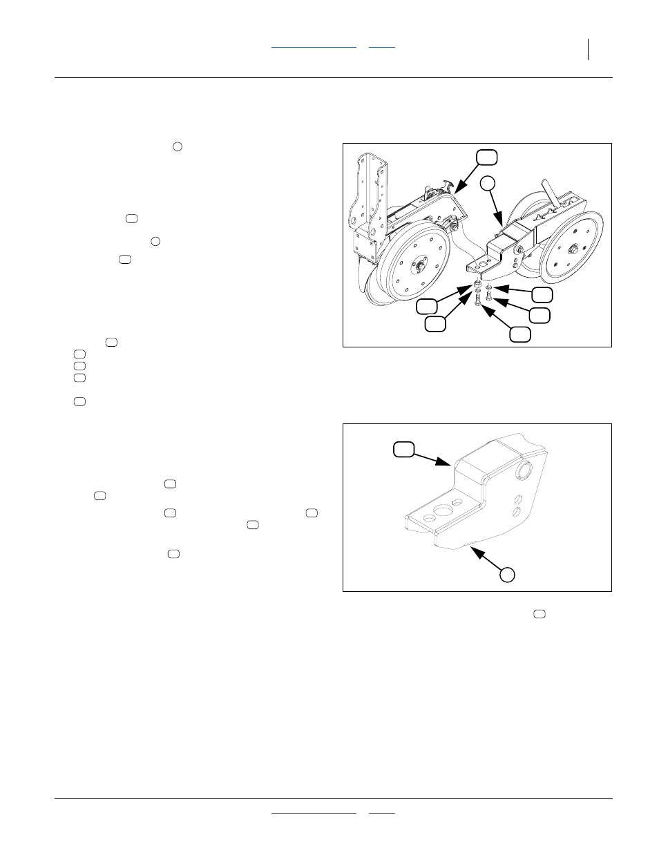
Press Wheel Installation
Refer to Figure 152
Press wheel assemblies
may be removed to meet
shipment clearance requirements. The removed
assemblies are found either in a crate, or a seed hopper.
Refer to Figure 153
There may be two types of press wheel assemblies:
• Long mount
assemblies, which are used on the
front (short) row of a twin pair. These mounts have a
series of notches
on the side.
• Mid mount
assemblies, which are used on the long
(rear) row of a twin pair. These mounts have smooth
sides.
Refer to Figure 152
For each row with press wheels dismounted:
20. Remove from the rear most two bolt holes of the
shank
and save one each:
405-032D 1X12 PW ADJUSTER
802-091C HHCS 1/2-13X1 1/2 GR5
802-258C HHCS 1/2-13X1 GR5
and two:
804-015C WASHER LOCK SPRING 1/2 PLT
Note: Do not disturb, loosen or remove the forward two
bolts.
21. Align the
1
⁄
2
inch holes in the press wheel assembly
with the
1
⁄
2
-13 tapped holes in the row unit.
Add a lock washer
to the
1
⁄
2
-13
×1 inch hex head
bolt
. Loosely screw into the rear
1
⁄
2
inch hole.
22. Add a lock washer
and the eccentric adjuster
to the
1
⁄
2
-13
×1
1
⁄
2
inch hex head bolt
. Loosely
screw into the forward
1
⁄
2
inch hole
23. Rotate the adjuster
to visually align the press
wheel assembly with the row unit, and tighten the
adjuster and bolts. See “Press Wheel Centering” on
page 76.
Figure 152
Press Wheel Installation
25383
21
6
22
37
24
37
27
19
7
20
21
22
24
27
37
Figure 153
Long Press Wheel Mount
32191
19
19
7
37
27
37
22
24
22