Disc spreaders and scrapers, 25 series row-unit side wheels – Great Plains YP1625A Operator Manual User Manual
Page 105
Great Plains Manufacturing, Inc.
Maintenance and Lubrication
101
2013-08-13
401-625M
Disc Spreaders and Scrapers
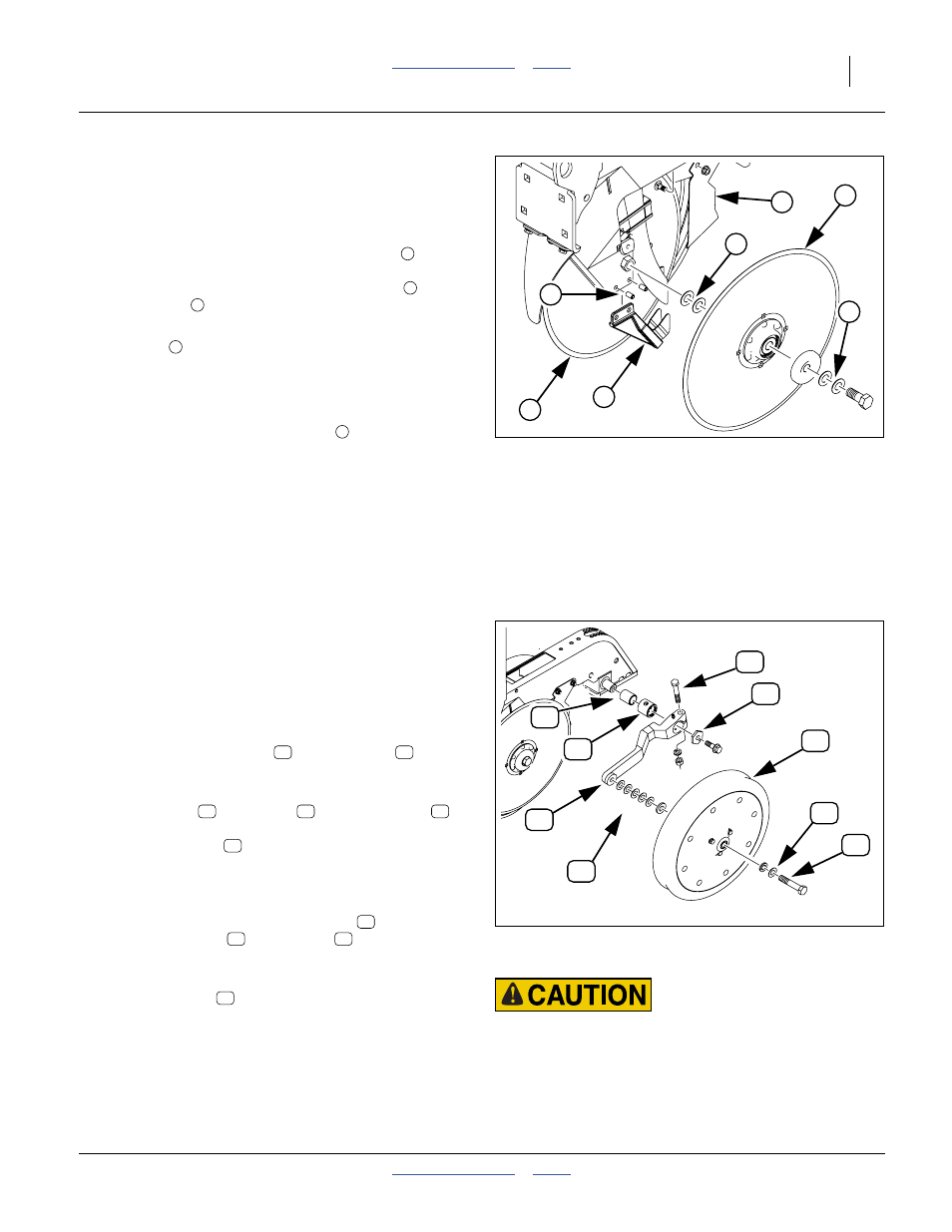
Refer to Figure 129
1.
Remove side gauge wheels from arms to access
row-unit discs and scrapers.
2.
With the unit raised, check blade spreader
for
wear. Replace spreader if it is
1
⁄
2
inch (13 mm) wide
or narrower. To replace, remove disc blade
, drive
out roll pins
, and install new spreader.
3.
When reinstalling disc blades, put two shim
washers
between bearing and shank on each
blade. Tighten bolts.
Note: You may need fewer inside shim washers on worn
discs.
4.
Check that outside disc scrapers
are formed to
disc blades to help remove any mud. Bend and twist
scrapers to fit blades as necessary. After every
200 acres (80 hectares) of operation, check outside
scrapers for proper adjustment and wear. Replace
outside scrapers as necessary.
25 Series Row-Unit Side Wheels
Figure 130
1.
Lift opener side wheel off the ground. Move tire in
and out to check for end play. Check for roughness in
bearing by rotating wheel. If bearings are rough,
inspect and replace if necessary.
2.
The side wheels are preset at the factory. However,
because of normal wear it may become necessary to
make adjustments so the wheel remains close to the
disc. Loosen clamp bolt
and slide arm
inward
to take up gap between side wheel and disc blade. If
more adjustment is needed, continue at step 3.
3.
Remove bolt
and wheel
. Remove shims
from the inside of wheel and place them on the
outside of wheel
. Always place removed shims
from the inside to the outside. When installed, wheel
should turn freely and not hit the arm at the curve.
Do not add any more shims than necessary.
4.
Disassemble side gauge wheel arm
from unit.
Remove bushing
from sleeve
and check for
wear. If necessary, replace bushing.
5.
When reinstalling side gauge wheels, align tab on
hex adjustment
with notch in bushing. Replace
bolt and tighten.
6.
Adjust side gauge wheels. See “Side Gauge Wheel
Adjustments” on page 66.
Note: It is normal for the blade spreader to have some
looseness in the holder and between the blades.
Some looseness is required for proper operation.
Figure 129
Spreaders and Scraper
s
22839
1
2
3
4
5
2
4
1
2
3
4
5
Sharp Object Hazard:
Be careful when working in this area.
Opener disc edges are sharp.
Figure 130
Adjusting Gauge Wheel Spacing
21894
14
11
17
16
10
18
13
15
12
{
10
11
12
13
14
15
11
16
17
18