2 hydraulic brake hook-up, 1 air brake hook-up – Great Plains CDA600 Operator Manual User Manual
Page 25
23
Centurion CDA600
270-600M-ENG
2013-06-14
By following these instructions
you will see that at NO point
in the coupling or decoupling
process has the red line been
left in the tractor on its own.
This is intentional and should be
considered the ‘rule’ to coupling
the hoses.
Do not use the Centurion with
a “single-line” air brake system.
This drill is designed for transport
speeds that require an air brake
system to be “dual-line”. A single-
line tractor system cannot charge
the tank that powers the drill
brakes.
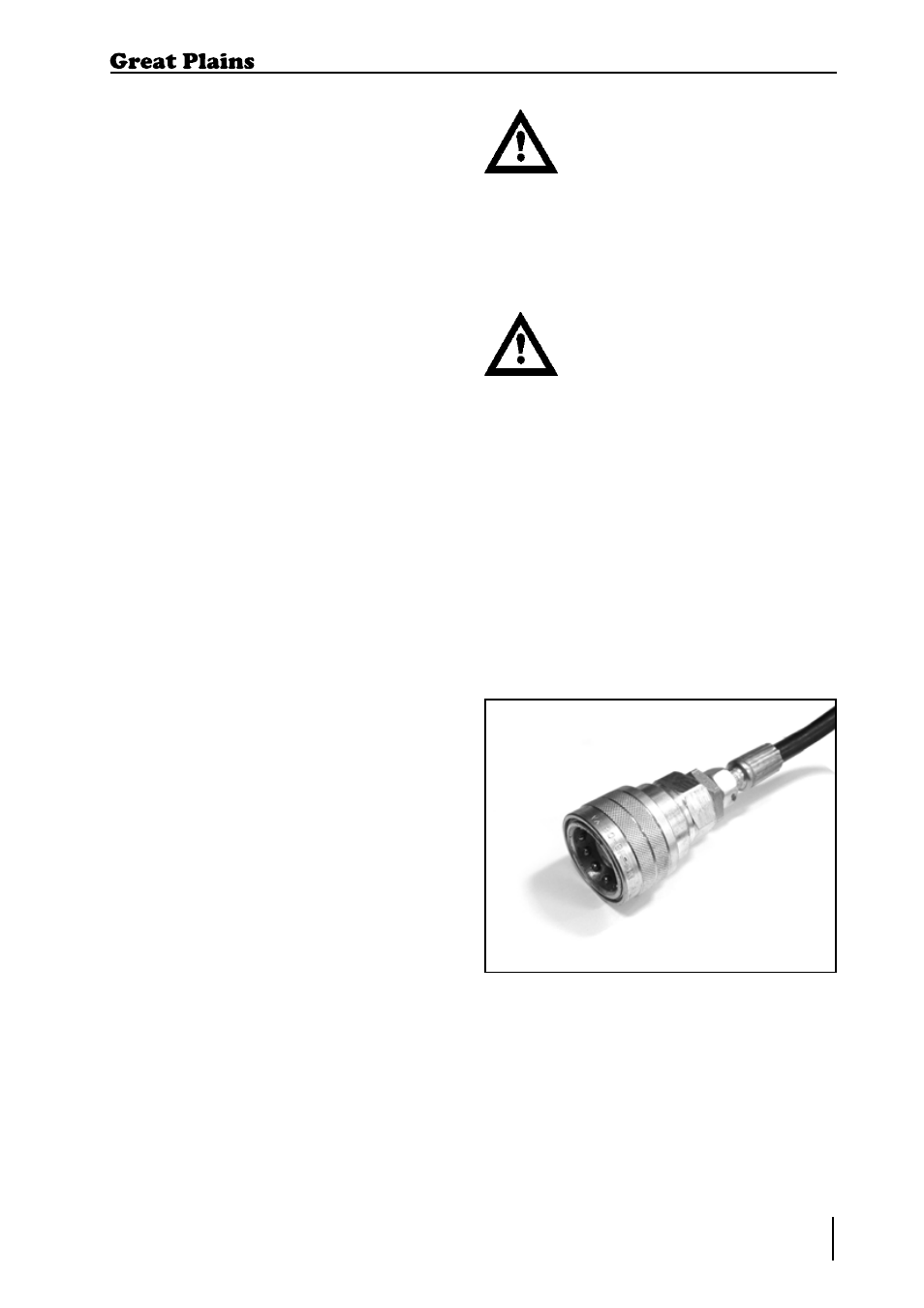
2.7.2 Hydraulic Brake
Hook-up
This is a single hydraulic line, connected to
the tractor “Brake” outlet. This has a female
connector.
2.7.1 Air Brake Hook-up
Please refer to the following procedure when
coupling or decoupling any item of Great
Plains machinery fitted with an AIR brake or
AIR and HYDRAULIC brake system. Please
note that this procedure does not apply to
any machines fitted with a HYDRAULIC
system ONLY.
When Coupling:
1.
Reverse up to the machine and
connect the machine to the tractor as
instructed to on page 21.
2.
With the machine connected couple
the air lines. When coupling ensure the
yellow line is attached first followed by
the red line.
3.
Your brake hoses are now attached
and are ready for operation.
4.
Continue with the coupling process as
instructed on page 21.
When De-coupling:
1.
Bring the machine to the parking
position as instructed to on page 31.
2.
With the machine still connected to
the tractor remove the red brake line
followed by the yellow line.
3.
Your brakes will now be ON and will
hold, ensuring they have been adjusted
and maintained correctly, the machine
in position. (note: if the machine‘s tank
is drained of air once all lines have
been detached the brakes will come off
(same situation as pushing the shunt
valve).
4.
Continue de-coupling the machine until
it is fully disconnected.
2. Transportation / Installation
Figure 2. Brake connection hose.