In100 mortise lock – SARGENT IN100 Mortise Locks User Manual
Page 9
6/30/12
1-800-810-WIRE • www.sargentlock.com • A8122A 9
Copyright © 2012, Sargen
t Manufacturing Company
, an A
SS
A AB
LO
Y G
roup company
. All right
s reser
ved
.
Reproductions in whole or in par
t without express writ
ten permission of Sargen
t Manufacturing Company is prohibited
.
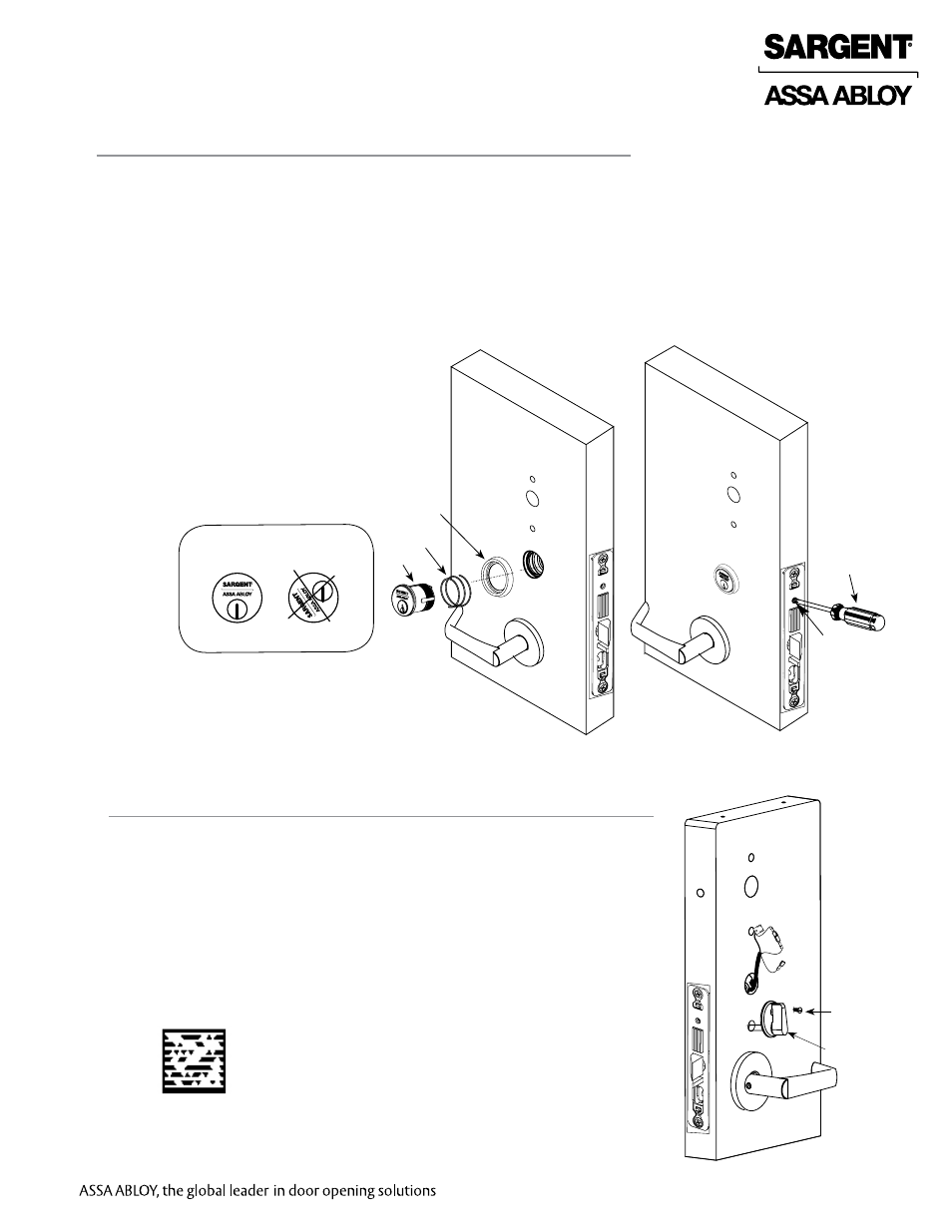
IN100 Mortise Lock
Fig. 6B
1. Slide the spring and the rosette onto the cylinder.
2. Rotate the cylinder into cylinder hole with fingers.
3. Insert key 75% of the way and utilize the key to rotate the cylinder into the rest of the cylinder hole.
Note: Do not attempt to tighten all the way.
4. Verify the orientation of the cylinder has the Sargent logo as depicted in Fig. 6A.
5. Hand tighten the cylinder clamp screw with Phillips screwdriver
to prevent unscrewing of the cylinder (Fig 6C).
6. Test cylinder function:
• Key retracts latchbolt and deadbolt
(7976 function). Key retracts latchbolt
(7978 function).
• Cylinder not present for 7977
and 7979 functions.
NOTE: Use lever handle holes
to manipulate lock to ease
thread engagement of cylinder.
Fig. 6C
Outside of Door
IMPORTANT: Position cylinder so that the
SARGENT logo is positioned correctly.
Correct Incorrect
Fig. 6A
6 Outside Cylinder Installation
7 Install Thumb Turn
Fig. 7
Thumb Turn
Inside of Door
Cylinder
Clamp-
Screw
Phillips
Screwdriver
1. Insert thumb turn into preparation hole and engage slot in lock body.
2. Orient mounting plate so screw hole is vertical (aligned with
preparation holes).
3. Secure plate with phillips screw provided.
4. Test thumb turn for function by retracting and projecting the deadbolt
(7976 and 7977 functions only).
Phillips
screw
Rosette
Spring
Cylinder
Scan this Microsoft® Tag using your mobile phone
to see a video of this installation step. The Microsoft
Tag mobile app is required to scan the Tag.
Download the free mobile app at http://gettag.mobi