In100 mortise lock, 4 assemble trim, 5 install inside rose and inside lever assembly – SARGENT IN100 Mortise Locks User Manual
Page 8
8 1-800-810-WIRE • www.sargentlock.com • A8122A
Copyright © 2012, Sargen
t Manufacturing Company
, an A
SS
A AB
LO
Y G
roup company
. All right
s reser
ved
.
Reproductions in whole or in par
t without express writ
ten permission of Sargen
t Manufacturing Company is prohibited
.
6/30/12
IN100 Mortise Lock
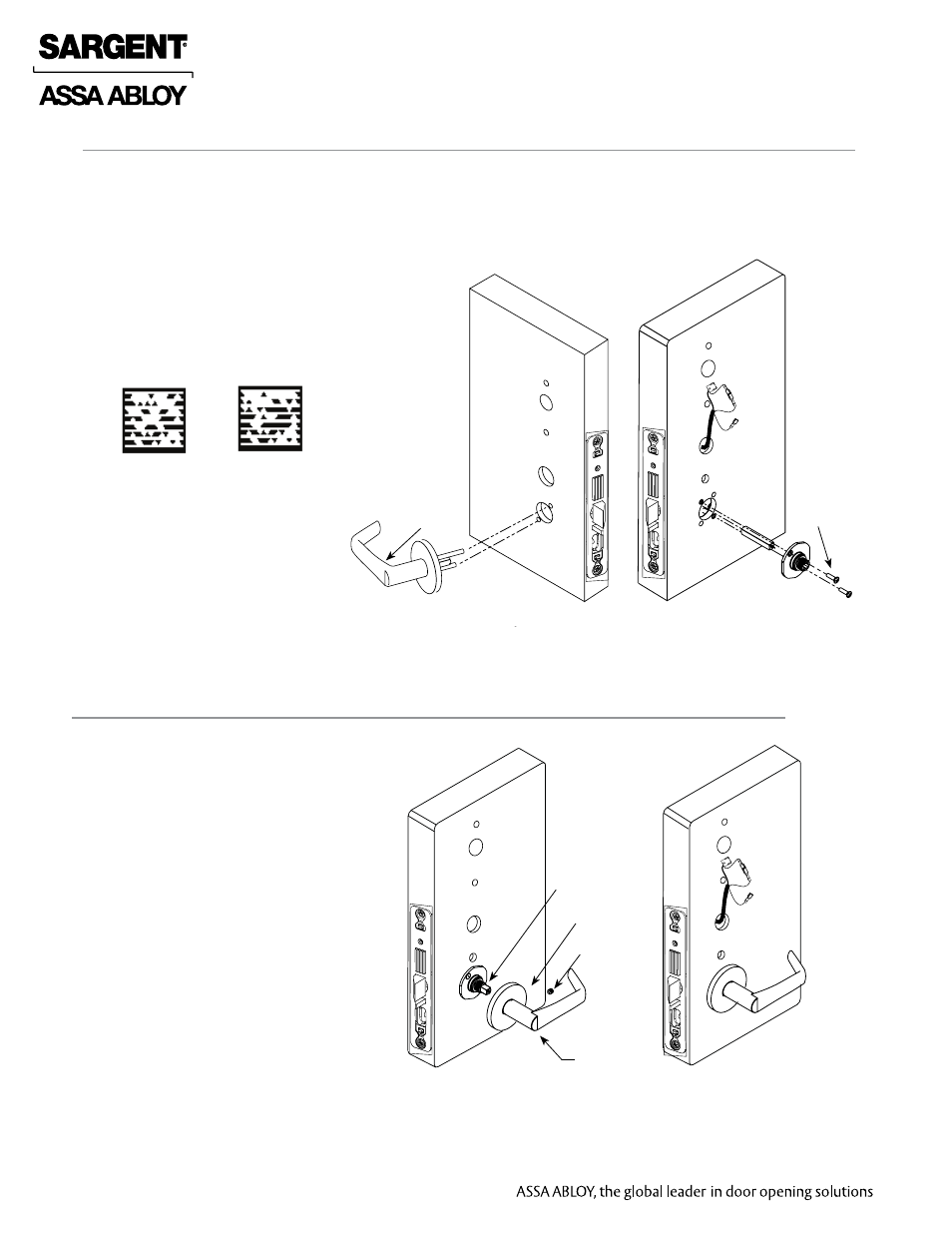
4 Assemble Trim
1. With outside lever horizontal, insert the mounting post through outside of door and lock body.
Make certain the lever spindle is properly engaged inside the lock body (Fig 4A).
2. On the inside of the door, insert spindle into square hole of mortise lock (Fig 4B).
3. Slide inside adapter and plate assembly over spindle and secure with (2) 8-32 X 5/8” Phillips
oval head and lock washer machine screws.
Fig. 4B
Fig. 4A
8-32 X 5/8”
Phillips
Oval
Head and
Lock
Washer
Machine
Screw
Inside of Door
Outside of Door
Fig. 5A
Fig. 5B
Set Screw
Inside Lever
Spindle
Rose
1. Rotate the inside rose first counter clock
wise to seat the threads then clockwise
to securely tighten.
2. Slide lever handle onto spindle until fully
seated. Be sure handle is horizontal and
facing the hinge side of the door. Push
lever onto spindle so minimum gap
is visible.
3. Tighten the set screw securely with
a T20 Torx.
4. Before closing the door, test that the
lever is functional and ensure
smooth operation of the
latchbolt.
5 Install Inside Rose and Inside Lever Assembly
Inside of Door
Outside Trim
Scan this Microsoft® Tag using your
mobile phone to see a video of this
installation step. The Microsoft Tag
mobile app is required to scan the
Tag. Download the free mobile app at
http://gettag.mobi
Assemble Trim
Inside Lever
Assembly