In100 mortise lock, 14 configuring rx switch handing, 15 battery housing wiring – SARGENT IN100 Mortise Locks User Manual
Page 13
6/30/12
1-800-810-WIRE • www.sargentlock.com • A8122A 13
Copyright © 2012, Sargen
t Manufacturing Company
, an A
SS
A AB
LO
Y G
roup company
. All right
s reser
ved
.
Reproductions in whole or in par
t without express writ
ten permission of Sargen
t Manufacturing Company is prohibited
.
IN100 Mortise Lock
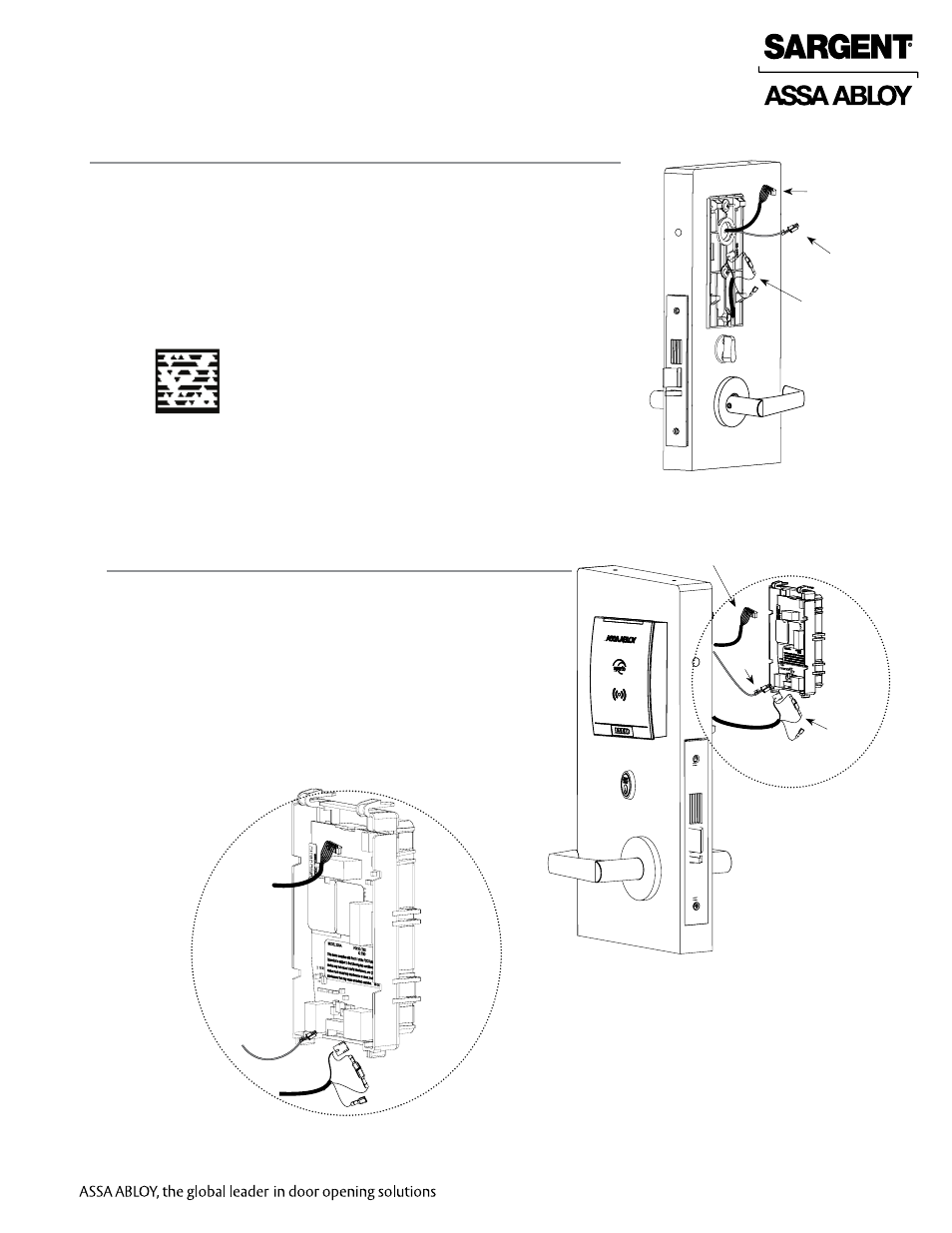
14 Configuring RX Switch Handing
1. Each lever handle has a sensor installed but only the inside lever is
utilized for RX sensing.
2. To properly configure the RX functionality, connect the terminals as
indicated below:
RH or RHRB door handing (blue to blue)
LH or LHRB door handing (yellow to blue)
3. Note: Factory default is blue to blue (right hand lock).
IMPORTANT: grasp each connector firmly before separating.
Do not pull wires apart.
Wire harness
Wire harness
DPS
Lock
body
wiring
15 Battery Housing Wiring
1. Connect the outside reader ribbon cable to the top of the
battery housing (See Fig.15B for detail).
2. Connect the DPS wire to the 3-wire header at the lower
left corner of the PCB.
3. Connect the lock body harness to the 5-wire header at
the lower right corner of the PCB.
IMPORTANT: Confirm the correct connector orientation
prior to assembly. Do not force connectors
4. Note: If the HID wire harness must be twisted to connect to
the battery housing the HID reader has been installed upside
down. Turn the HID reader right side up and reinstall, then
connect.
Lock
body
wiring
DPS
Fig. 15A
Fig. 15B
Inside of Door
Fig. 14
Scan this Microsoft® Tag using your mobile
phone to see a video of this installation
step. The Microsoft Tag mobile app is
required to scan the Tag. Download the free
mobile app at http://gettag.mobi