In100 mortise lock, Lock led indications – SARGENT IN100 Mortise Locks User Manual
Page 17
6/30/12
1-800-810-WIRE • www.sargentlock.com • A8122A 17
Copyright © 2012, Sargen
t Manufacturing Company
, an A
SS
A AB
LO
Y G
roup company
. All right
s reser
ved
.
Reproductions in whole or in par
t without express writ
ten permission of Sargen
t Manufacturing Company is prohibited
.
IN100 Mortise Lock
The lock has three LED lights that support an optical scheme with red, yellow and green.
The indication scheme is described by the figures below:
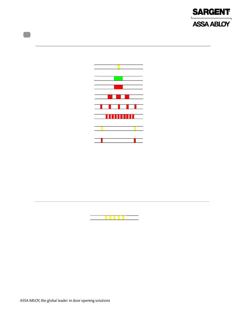
Fig. Lock Normal operation LED indication
Lock LED Indications
9
NOTE: When the lock mechanism is blocked (lock jammed) the lever must be turned to release it.
The “Error in lock” indication is also shown instead of the POST flashes if the battery is not accepted
as new after a power-on-reset.
1 Lock Normal Operation LED indication
2 Lock Maintenance LED Indication
Some special LED indication schemes are used during lock maintenance actions:
Enter configuration
mode
Five yellow flashes (.125 s each)
Fig. Lock maintenance LED indication
Card read
(configurable)
Access granted,
EAC offline or online
Access denied,
EAC online
Access denied,
EAC offline
Lock mechanism is
blocked when closing
Error in lock,
maintenance required
Time to replace the battery
Battery reached end of life,
lock disabled
One yellow flash (.25 second)
One green flash (1 second)
One red flash (1 second)
Three red flashes (.5 s each)
Continuous red flashes blocked when
closing (.125 seconds every 1 second)
Ten red flashes (.125 s each), maintenance
required; repeated if lock can’t close
Continuous yellow flashes
(.25 seconds every 5 seconds)
Continuous red flashes of life,
(.25 seconds every 5 seconds)