2 classic+ range operating parameters – Viking Pump TSM285: Classic+ Lobe Pump User Manual
Page 5
SECTION TSM 285
ISSUE
A
PAGE 5 OF 36
2.7 STANDARD PUMP
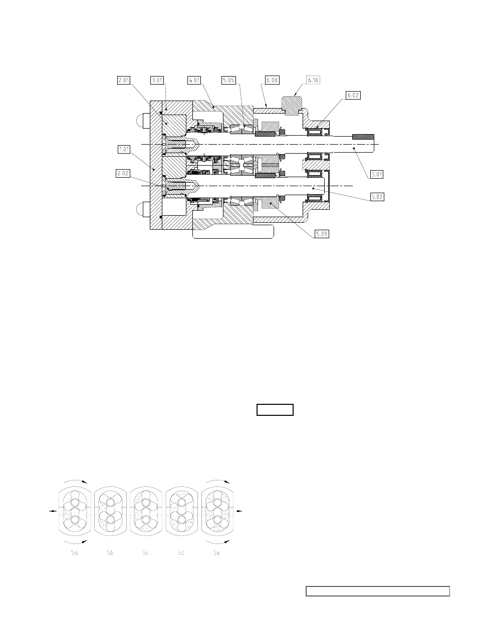
COMPONENT TERMS
3.0 GENERAL
3.1 CLASSIC+ PUMPING PRINCIPAL
The pumping action of the rotary lobe pump principle is
generated by the contra rotation of two pumping elements
(rotors) within a chamber (casing) - see Figure 5. The rotors are
located on shafts, which in turn are mounted within an external
gearbox and supported by the bearings; the timing gears are
also located on the shafts. The timing gears transfer the energy
from the drive shaft to the driven shaft, synchronizing the rotors
such that they rotate without contact with each other.
As the rotors pass the suction port, see Figure 5a, the cavity
generated increases creating a pressure decrease, which
induces the pumped medium to flow into the casing.
The pumped medium is carried around the casing by the rotors;
see Figure 5b and 5c, to the discharge side of the pump, Figure
5d. Here the cavity decreases and the pumped medium is
discharged from the casing, Figure 5e.
For pump component terms, see Figure 4.
3.2 CLASSIC+ RANGE OPERATING
PARAMETERS
The maximum pressure and speed operating parameters are
given in Figure 6. In practice these may be limited due to the
nature of the product to be pumped and/or design of the system
in which the pump is to be installed. Consult Viking Pump or
your Viking Pump distributor for assistance.
The operating temperature limit of the pump is determined
by the rotor clearance. For the CP10, CP20, CP30 and CP40
series pumps there are three rotor clearance bands (class A,
B and C), and two (class B and D) for the CP50 series pumps.
If the system or product characteristics are to
be changed from the original application for
which the pump was selected, Viking Pump or
their authorized distributor should be consulted
to ensure the pump is suitable for the new
application.
The pump should not be subjected to sudden temperature
changes to avoid the risk of damage from sudden expansion/
contraction of components. Care should be taken when
selecting pumps for handling liquids containing abrasive
particles as these may cause wear of pump head components.
For advice or assistance contact Viking Pump or your Viking
Pump distributor.
ROTORS
FRONT COVER
ROTOR
RETAINER
ROTORCASE
BEARING
HOUSING
FRONT
BEARINGS
GEARBOX
COVER
BREATHER
/FILLER CAP
REAR
BEARINGS
DRIVE
SHAFT
DRIVEN
SHAFT
TIMING
GEARS
figure 4
Pump Component Terms
figure 5
Rotary Lobe Pumping Principle
WARNING