4 cp50 single flushed mechanical seal replacement, 2 cp50 single mechanical seal replacement – Viking Pump TSM285: Classic+ Lobe Pump User Manual
Page 28
SECTION TSM 285
ISSUE
A
PAGE 28 OF 36
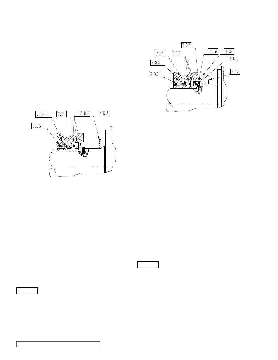
- Remove head (1.01), rotor caps (2.02), O-rings (2.03),
retainers (2.05), rotors (2.01), O-rings (2.04) and casing
(3.01) refer to sections 4.3.1 and 4.3.2.
- Remove rotary seal cartridge assemblies (7.05) with O-ring
(7.01) from shafts (5.01 and 5.02) by simply sliding off.
Do not loosen screws in rotary seal cartridge assemblies
(7.05).
- Remove housings (7.06) complete with lipseals (7.08) and
O-rings (7.07) from shafts (5.01 and 5.02).
- Remove lipseals (7.08) and O-rings (7.07) from housings
(7.06).
- Remove stationary seal seats (7.04) and O-rings (7.02) from
casing (3.01).
5.3.4 CP50 SINGLE fLUSHED
MECHANICAL SEAL
REPLACEMENT
Refer to Figure 55
- Install O-rings (7.02) to stationary seal seats (7.04).
- Install stationary seal seats (7.04) to casing (3.01) ensuring
correct location of O-rings (7.02).
Note: The stationary seal seat (7.04) has a
triangular shape, which must locate fully into
the casing (3.01), bore.
- Install lipseals (7.08) and O-rings (7.07) to housings (7.06).
- Install housings (7.06) to shafts (5.01 and 5.02).
- Install rotary seal cartridge assemblies (7.05) with O-ring
(7.01) to shafts (5.01 and 5.02) ensuring engagement of
drive slots with pins (5.23) in shafts (5.01 and 5.02).
- Install casing (3.01), O-rings (2.04), rotors (2.01), retainers
(2.05), O-rings (2.03), rotor caps (2.02) and head (1.01) -
refer to section 4.3.5.
- Secure housings (7.06) to casing (3.01) with nuts (7.18).
- Remove head (1.01), rotor caps (2.02), O-rings (2.03),
retainers’ (2.05), rotors (41), O-rings (2.04) and casing
(3.01), refer to sections 4.3.1 and 4.3.2.
- Remove rotary seal cartridge assemblies (7.11) with O-ring
(7.01) from shafts (5.01 and 5.02) by simply sliding off.
Do not loosen screws in rotary seal cartridge assemblies
(7.05).
- Remove stationary seal seats (7.04) and O-rings (7.02)
from casing (3.01).
5.3.2 CP50 SINGLE MECHANICAL
SEAL REPLACEMENT
- Install O-rings (7.02) to stationary seal seats (7.04).
- Install stationary seal seats (7.04) to casing (3.01) ensuring
correct location of O-rings (7.02).
Note: The stationary seal seat (7.04) has a
triangular shape, which must locate fully into
the casing (3.01), bore.
- Install rotary seal cartridge assemblies (7.11) with O-ring
(7.01) to shafts (5.01 and 5.02) ensuring engagement of
drive slots with pins (5.23) in shafts (5.01 and 5.02).
- Install casing (3.01), O-rings (2.04), rotors (2.01), retainers
(2.05), O-rings (2.03), rotor caps (2.02) and head (1.01)
- refer to section 4.3.5.
- Install casing (3.01), O-rings (2.04), rotors (2.01), O-rings
(2.03), rotor retainers (2.02) and head (1.01) refer to sections
4.1.4 (CP20/CP30) or 4.2.5 (CP40).
- Secure housings (7.06) to casing (3.01) with screws (7.10)
ensuring correct location onto dowels (7.09).
- Rotate pump shafts by two or three full revolutions.
- If not already tightened, tighten screws in rotary seal cartridge
assemblies (7.11) to correct torque, refer to section 8.2.
Note: Access to screws in rotary seal cartridge assemblies
(7.11) is through the flush connections of housings (7.06).
5.3 CP50 MECHANICAL SEALS
5.3.1 CP50 SINGLE MECHANICAL
SEAL REMOVAL
5.3.3 CP50 SINGLE fLUSHED
MECHANICAL SEAL REMOVAL
Refer to Figure 55.
figure 55
Single flushed Mechanical Seal CP50
figure 54
Single Un-flushed Mechanical Seal CP50
WARNING
WARNING